elsner elektronik 40115 Technische Daten und Installationsanweisungen - Seite 6
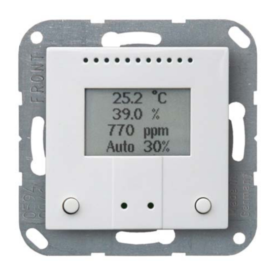
Blättern Sie online oder laden Sie pdf Technische Daten und Installationsanweisungen für Zubehör elsner elektronik 40115 herunter. elsner elektronik 40115 9 Seiten. Indoor sensor and ventilation control

2.3.2. Connection board
1
3
Ventilation Control AQS/TH PF • Version: 31.01.2017 • Technical changes and errors excepted.
Fig. 2
1
Slot CO
2
Socket for 8-wire connecting cable, see Fig. 4
3
Plug CO
4
CO
Cable length of CO
a
Hole distance approx. 43 mm
b
Membrane diameter approx. 18 mm
2
Fig. 3
8-wire connecting cable for control outputs, inputs
and operating voltage:
blue
black
purple
black
yellow
black
white
black
6
sensor unit
2
sensor unit
2
sensor unit
2
sensor approx. 110 mm.
2
4
Output 2
(OPEN window, Ventilator level 2)
Output 1
(CLOSE window, Ventilator level 1)
Supply voltage for output 1+2
Input 2 (OPEN/+)
Input 1 (CLOSE/-)
Supply voltage for input 1+2
Operating voltage GND
Operating voltage +24 V
Installation and start-up
b
a
