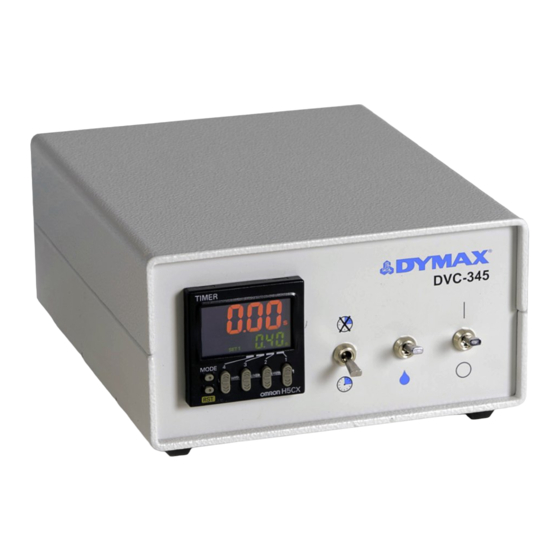
dymax T11146 Benutzerhandbuch - Seite 9
Blättern Sie online oder laden Sie pdf Benutzerhandbuch für Controller dymax T11146 herunter. dymax T11146 16 Seiten. Valve controller

Table 1.
Dispensing Valve Plumbing Configurations
Valve Diagram
AIR IN
AIR IN
MATERIAL IN
U S E R G U I D E
D V C - 3 4 5 V A L V E C O N T R O L L E R
|
Plumbing Instructions
Model 300: Single-acting, normally closed diaphragm
valve.
Plug Port No. 1 (normally open) on the back of the
controller and plumb Port No. 2 (normally closed) to
the Air-In Port on the dispensing valve.
Model 455: Single-acting, normally closed pinch
valve.
Plug Port No. 1 (normally open) on the back of the
controller and plumb Port No. 2 (normally closed) to
the Air-In Port on the dispensing valve.
Model 475: Single-acting, normally closed diaphragm
valve.
Plug Port No. 1 (normally open) on the back of the
controller and plumb Port No. 2 (normally closed) to
the Air-In Port on the dispensing valve.
Model 775: Single-acting, normally closed spool
valve.
Plug Port No. 1 (normally open) on the back of the
controller and plumb Port No. 2 to the Air-In Port on
the dispensing valve.
Model 826: Single-acting, normally closed pinch
valve.
Plug Port No. 1 (normally open) on the back of the
controller and plumb Port No. 2 to the Air-In Port on
the dispensing valve.
9
