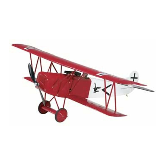
GREAT PLANES Fokker D.VII ARF ElectriFly Gebrauchsanweisung - Seite 9
Blättern Sie online oder laden Sie pdf Gebrauchsanweisung für Spielzeug GREAT PLANES Fokker D.VII ARF ElectriFly herunter. GREAT PLANES Fokker D.VII ARF ElectriFly 20 Seiten.

❏
14. Temporarily attach the elevator to the stabilizer with
four CA hinges. Note: There is a left and right side to the
elevator. The left side of the elevator has a small slot for the
elevator control horn. The slot is located under the covering.
(The covering will be cut away in a later step in the manual.)
Locate the slot by pressing the underside of the elevator. Be
sure the elevator half with the slot is on the left side of
the fuselage. Make sure the stabilizer and elevator are
aligned. If needed, use T-pins to hold the CA hinges
centered in the elevator. Apply 3 drops of thin CA on the top
and bottom of each hinge.
❏
15. Install three CA hinges in the rudder and test fit it on
the fin. Adjust the position of the fin so that the bottom of the
rudder is even with the bottom of the fuselage and the LE of
the rudder and the TE of the fin are aligned. Apply 3 drops
of thin CA on each side of each hinge.
❏
16. Test fit the tail skid at the rear of the fuselage. When
satisfied with the fit, attach the tail skid to the bottom of the
fuselage using medium CA.
RADIO INSTALLATION
Install the Motor & ESC
Note: You will need to have your motor battery charged later in
this section. We recommend that you start charging it now so
you do not have to wait for it to charge later. Make sure to closely
follow the charging instructions for charging LiPo batteries.
We also recommend that you remove the bottom wing for
this procedure for better access to the inside of the fuselage.
❏
1. Cut a 20mm [3/4"] long piece of hook and loop material
(not included). Glue the 20mm [3/4"] soft piece (hook side) to
the back of the ESC. Glue the rough piece (loop side) to the
bottom of the battery tray. Insert the ESC through the front of
the firewall and secure it in place by joining the hook and loop
material. Route the battery connector out of one of the two
holes at the back of the battery compartment. Route the servo
lead into the wing opening and the three motor leads out the
front of the firewall. The reason the ESC needs to be mounted
in this location is so that it has a good flow of air over it.
❏
2. Cut another 20mm [3/4"] long piece of hook and loop
material (not included) and glue the 20mm [3/4"] soft piece
(hook side) to the back of the receiver. Glue the rough piece
(loop side) to the top of the inside of the fuselage in front of
the cockpit. Insert the receiver and secure it in place by
joining the hook and loop material.
❏
3. Use epoxy to join the two piece motor mount. Make
sure all openings are flush.
9
