Dynamatic 4000 Anleitungsblatt - Seite 10
Blättern Sie online oder laden Sie pdf Anleitungsblatt für Controller Dynamatic 4000 herunter. Dynamatic 4000 14 Seiten. With dancer position
Auch für Dynamatic 4000: Anleitungsblatt (15 seiten), Anleitungsblatt (13 seiten), Anleitungsblatt (13 seiten), Anleitungsblatt (14 seiten)

indicates that the speed of the drive is in the regulating range of the controller. The clutch voltage
should drop below 45V. This will be approximately the maximum rated speed of the drive. The
maximum speed point setting will vary with differed mechanical units.
There are two other conditions for which the LED will be out besides the drive being set for zero
speed or running wide open above the regulating range. These are whenever the "E" relay is
deenergized (the drive is stopped), or due to a wiring error, ground or some malfunction of the
controller itself.
Max Speed/Volts R21, Alternate Methods
a. To set maximum rated speed with a tach or stroboscope: turn the Run Speed potentiometer
R5 to 100% (Full CW). Allow the drive to accelerate to full speed, turn to Max Speed/Volts pot
CW until the rated speed indicated is the same as the speed listed on the nameplate of the
mechanical unit.
b. To set approximate maximum speed with a voltmeter connect a voltmeter (60 Vac scale)
across terminals G1 and G2. Turn the Run Speed pot R5 to 100% (Full CW) Allow the drive to
accelerate to full speed. With the drive at full speed, turn the Max Speed/Volts pot CW until
the meter reading ceases to rise. Back off the adjustment (CCW) until the meter reading just
begins to drop. This is the point of maximum speed.
c. To set a maximum speed that is less than rated maximum speed requires the use of a
tachometer or stroboscope indicator. This cannot be accomplished with the LED status
monitor. Turn the Run Speed potentiometer to 100% (Full CW). Allow the drive to accelerate
to full speed. With the drive at full speed, slowly increase Max Speed/Volts potentiometer
setting CW until the desired speed is indicated.
5. Since there may be some interaction between the Zero Adjust and the Max Speed/Volts,
particularly if the minimum speed is other than zero, repeat steps 3 and 4 until the desired speeds
are obtained for both the zero and max positions of the Run Speed pot.
6.
Time Constant (TC) adjust
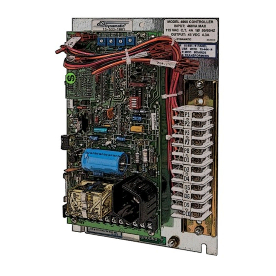
and a variable RC combination to simulate the different coil time constants of various size drives.
A trimpot illustration is provided to facilitate the setting of this control. Sufficient range has been
provided for drive sizes from fractional though 20 hp for the 4000 controller and up to 125 hp for
the 4050 controller. Set your TC control appropriately for your individual drive size as shown in
Preliminary Adjustments. Settings are not critical and so may be "tuned" for each drive. High
inertia applications can benefit from a higher than normal setting.
7.
Current Feedback R20*-
Applications are best met with a negative current feedback response which is slower in settling
and less likely to overshoot at low rpms. There are some low inertia, light load, linear acceleration
applications that may also benefit from improved low-end linearity with current feedback
damping. If you have one of these applications, remove Jumper J1 from the Normal position and
10
R26- The TC Adjust is used to set current feedback by using coil voltage
Normal operation will not require use of this potentiometer. Certain
