Automationdirect.com Productivity 1000 P1-04RTD Handbuch - Seite 3
Blättern Sie online oder laden Sie pdf Handbuch für E/A-Systeme Automationdirect.com Productivity 1000 P1-04RTD herunter. Automationdirect.com Productivity 1000 P1-04RTD 8 Seiten. Analog input

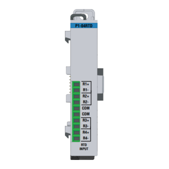
P1-04RTD Schematic
INTERNAL MODULE
R1+
R1-
R2+
R2-
COM
COM
R3+
R3-
R4+
R4-
ANALOG CIRCUIT COMMON
Sales 800-633-0405
CIRCUITRY
CH1 RTD
INPUT
CH2 RTD
INPUT
CH3 RTD
INPUT
CH4 RTD
INPUT
P1-04RTD Wiring Diagram
Resistance Input
R+
R-
COM
1. R+, R-, and COM wires to an
RTD must be equal length and
type. Refer to RTD manufacturers
Notes for maximum accuracy:
3. Do not use cable shield as a
sensing wire.
4. When applicable, connect shield to
RTD common only, otherwise connect
to module common only. Do not
connect shield to both ends.
5. Jumper unused inputs to common.
R+
R-
COM
www.productivity1000.com
RTD Input Circuits
2-wire RTD
R+
R-
COM
Note: Connect two wires to
one side of a two-wire RTD.
2. For 2-wire RTD, attach a third wire to
module common.
3-wire RTD
R+
R-
COM
4-wire RTD
R+
R-
COM
Note: Leave 4th
wire unattached as shown.
3
