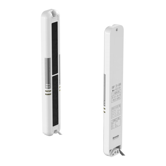
Autonics BWP20-12 Schnellstart-Handbuch - Seite 4
Blättern Sie online oder laden Sie pdf Schnellstart-Handbuch für Sicherheitssensoren Autonics BWP20-12 herunter. Autonics BWP20-12 5 Seiten.

Installations
■ For direction of installation
Emitter and receiver should be installed in same up/down direction.
Emitter
Receiver
■ For reflection from the surface of wall and flat
When installing it as below, the light reflected from the surface of wall and flat is not
shaded. Please check whether it operates normally or not with a sensing target before
using. (interval distance: ≥ 0.3 m)
Emitter
Receiver
Sensing target
Reflecting
light
Floor
■ For protection of interference
It may cause interference when installing more than 2 sets of the sensor. In order to
avoid the interference of the sensor, please install as following figures and use the
transmitted light frequency changing function.
• Transmission direction should be opposite between 2 sets.
Receiver1
Emitter1 Emitter2
Emitter1
Receiver1
Emitter1
Receiver1
Receiver2
Emitter2
Emitter1
Receiver1
Receiver2
Emitter2
• Baffle should be installed between 2 sets.
Emitter1
Receiver1
• It should be installed out of the interference distance.
: It may be a little different based on installation environment.
: A void using the unit in the place where the sensor is exposed directly to the fluorescent
light with high speed start or high frequency.
Emitter1
Receiver1
Emitter2
Receiver2
L (m)
Emitter
Emitter
Sensing target
Reflecting
light
Wall
Receiver2
Emitter2
Receiver2
Emitter1
Receiver1
Emitter2
Receiver2
Emitter1
Receiver1
Emitter2
Receiver2
Emitter2
Receiver2
Baffle
L
D
(sensing distance)
(installation allowable distance)
0.1 ~ 1 m
≥ 0.2 m
≥ 1 m
≥ 0.3 m
Feature Data
■ Parallel shifting characteristic
Receiver
Receiver
Receiver
■ Angle characteristic
Receiver
5
4
Emitter
3
2
1
0.1
250
150
Left ← Center → Right
Sensing area ℓ (mm)
8
6
Emitter
4
2
50
30
Left ← Center → Right
Operation angle Θ (°)
50
0
50
150 250
10
0
10
30
50
