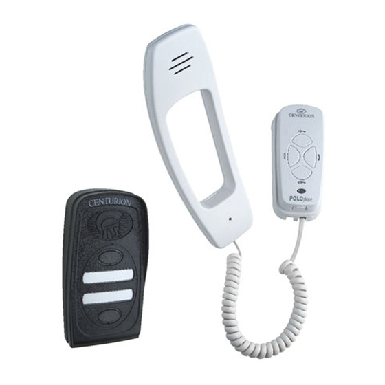
Centurion POLOphone Installationshandbuch - Seite 11
Blättern Sie online oder laden Sie pdf Installationshandbuch für Intercom System Centurion POLOphone herunter. Centurion POLOphone 17 Seiten. Entry panel
Auch für Centurion POLOphone: Installationshandbuch (17 seiten), Installationshandbuch (16 seiten), Verfahren für die Inbetriebnahme (4 seiten)

9
80mm
80mm
Tighten cable tie ensuring that there is
sufficient slack to terminate the cable
onto the electronics (±80mm).
12
Terminate onto the electronics.
Refer to the wiring diagram (See page
10)
15
A
Clip the (A) long tail end of the
telephone cord into the jack provided
at the bottom of the cradle and
similarly into the handpiece. Replace
the handpiece onto the cradle.
10
CABLE ROUTE
CABLE ROUTE
Terminate cable onto electronics.
Refer to wiring diagram (See page
10).
13
Using a sharp knife carefully cut out
the cable entry slot to allow the
surface mounted cable to route into
Wiring the status LED
Wiring the status LED
1
Connect the wires from the status
LED on the gate motor to the
terminals.
HANDSET INSTALLATION
11
CONCEALED
CONCEALED
If the cable is surface mounted,
route the cable into the unit from
underneath as shown. Secure to
cradle base using cable tie provided.
Allow sufficient slack (±80mm)
14
Clip the cradle back onto the base.
NB: It will be necessary when
commissioning the unit to have
the cradle cover removed.
2
Insert the wire from the LED drive in
the gate motor into the terminal
marked with a ( ).
Insert the wire from the COM/- from
the gate motor into the terminal
marked with a ( ).
Polophone Intercom - Page 11
80mm
80mm
*
*
