ALIBI ALI-CD700WAIR Installations- und Benutzerhandbuch
Blättern Sie online oder laden Sie pdf Installations- und Benutzerhandbuch für Sicherheitskamera ALIBI ALI-CD700WAIR herunter. ALIBI ALI-CD700WAIR 3 Seiten. Infrared mini dome camera
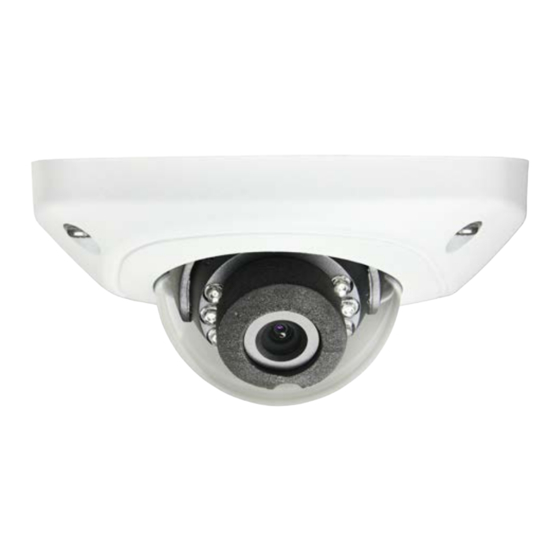
ALI-CD700WAIR Infrared Mini Dome
Camera Installation and User Guide
The ALIBI ALI-CD700WAIR dome camera include a new generation sensor with high sensitivity and
advanced circuit design technology. It features high resolution, low image distortion and low noise features
which makes them suitable for surveillance and image processing systems.
Features
High resolution color sensor: 700 TV Lines
•
IR cut filter enables the day/night surveillance
•
Auto white balance with high color rendition
•
Auto electronic shutter control adapts to different surveillance environments
•
Auto gain control, adaptive brightness
•
Internal 3-axis adjustment
•
Weather protection: IP66 rated
•
1.83"
ALI-CD700WAIR camera assembly front and side views
Drop cable
Hole for
cover
screw (4)
Jack for
video test
cable
Hole for
mounting
screw
IR array
Lens
Base
assembly
ALI-CD700WAIR camera internal components
www.observint.com
1
3.92"
3.82"
Microphone
What's in the box
Camera assembly
•
Drill template
•
Video test cable
•
Adjuster (for camera module)
•
Security L- wrench
•
Mounting hardware (screws and wall inserts)
•
Pad
•
This manual
•
Video test cable
Adjuster
Tools you need
To install the camera, you will need:
12 Vdc power source. See Specifications for voltage and wattage requirements.
•
Tools and additional fasteners (may be required) for mounting the camera
•
Video, audio and power extension cables
•
CCTV video setup monitor (optional)
•
Installation
Before installation:
Make sure that the device is in good condition and all the assembly parts are included.
•
Check the specification of the products for the installation environment.
•
Make sure that the wall or the ceiling is strong enough to withstand 3 times the weight of the camera.
•
To avoid fire or shock hazard, use only UL listed power supplies. Verify that the power supply will
•
provide the rated voltage and wattage for the camera. See the Specifications section.
OSD
During installation:
joystick
Camera Lens: Handle the camera carefully to prevent scratching or soiling the lens. If the lens or IR
•
array shield becomes soiled, clean it only with approved products. See the
Hole for
Monitor impedance: Set the monitor impedance switch to 75 Ω.
•
mounting
Power supply: Camera drop cable: The camera drop cable includes two connectors:
•
screw
Video BNC connector: For transmission of the video signal across a coax (75 Ω) BNC extension
—
Pan
cable.
adjust.
Power connector: When applying Vdc power, observe the power polarity. See the picture
—
lock screw
above for connector polarity configuration.
Camera
Audio BNC connector: Connect the audio drop cable to a coax (75 Ω) BNC extension cable.
module
—
1.
Using the drill template provided with your camera, mark the location of the two screws that anchor
the base assembly to the mounting surface. If you are routing the drop cable through base, also
mark the position of the hole for the drop cable. (See the template above.)
Power
Connector
Audio BNC
Connector
Camera drop cable connectors
Security L-wrench
Mounting
hardware
Pad
Video BNC
Connector
section.
Cleaning
ALI-CD700WAIR_CQ
10/21/14