A-M Systems 2200 Gebrauchsanweisung - Seite 5
Blättern Sie online oder laden Sie pdf Gebrauchsanweisung für Kontrolleinheit A-M Systems 2200 herunter. A-M Systems 2200 19 Seiten. Analog stimulus isolator

indirectly attached to the Model 2200 output. Some kinds of connectors (e.g. BNC
connectors) have exposed metal parts which may float at dangerous potentials unless
externally connected to safety ground. For greatest safety, turn the Model 2200 off
before handling connections to the output.
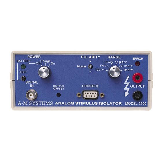
The instrument is very simple to operate. First, check the battery condition: set the Power
switch to off, and push the Battery Test button. The Test light should come on, indicating an
adequate charge. Connect your input signal to the Signal In connector. Set the Polarity
control to the predominant polarity of the waveform. Connect the Output to the stimulation
electrode (or other load you wish to drive) and set the Range switch to the correct scale. If
you wish to tum the output signal on or off by a separate controller (e.g. a timing signal), or be
able to test the batteries via computer control during the course of an extended experiment,
connect the control signal to the Control/ Gate input. Now tum the Power switch to On.
The output may go to an unpredictable state if the battery charge is not maintained. It is the
user's responsibility to ensure an adequate battery charge. Regular use of either front-panel
or control-port battery testing is sufficient to guarantee proper battery charge.
The Error indicator should remain unlit in normal operation. The Error LED will light when the
computer-interface battery test is in operation. Be aware, however, that the Error LED will not
light if the batteries are dead! It is normal for the LED to turn on briefly when the front panel
controls are switched.
To recharge the batteries, connect the battery charger to the rear Charger input, and set the
Power switch to Charge. Note that if the switch is left in the Charge position without any
incoming electrical power, the batteries will very slowly, but certainly, become discharged.
Signal Control
The voltage at the Signal In BNC defines the output waveform. The signal is DC coupled
across the optical isolation barrier, so virtually any waveform can be used. It can be turned
on and off with a digital Gate signal through the Control port
Set the Range control to achieve the type (voltage or current) and amplitude of output
required. The output power is limited to 100V (±50V in bipolar mode) and ±5mA. For
A-M Systems
Operating Instructions
PO BOX 850, Carlsborg, WA 98324 USA
Telephone: 800-426-1306 * 360-683-8300 * FAX: 360-683-3525
E-mail: [email protected] * Website: http://www.a-msystems.com
2
