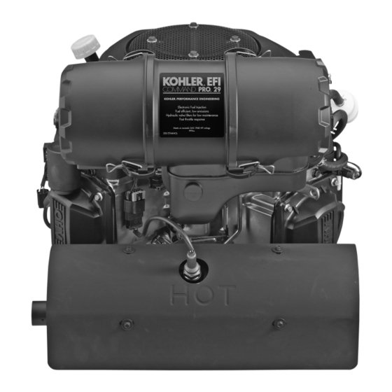
Kohler Command PRO ECV630 Benutzerhandbuch - Seite 9
Blättern Sie online oder laden Sie pdf Benutzerhandbuch für Motor Kohler Command PRO ECV630 herunter. Kohler Command PRO ECV630 21 Seiten. Vertical crankshaft
Auch für Kohler Command PRO ECV630: Benutzerhandbuch (8 seiten)

3. Before removing the oil filter, clean the area
around the oil filter to keep dirt and debris out
of the engine. Remove the old filter. Wipe off the
surface where the filter mounts. See Figure 6.
Oil Filter
Figure 6. Oil Filter and Oil Drain Plug.
4. Place a new replacement filter in a shallow pan
with the open end up. Pour new oil, of the proper
type, in through the threaded center hole. Stop
pouring when the oil reaches the bottom of the
threads. Allow a minute or two for the oil to be
absorbed by the filter material.
5. Apply a thin film of clean oil to the rubber gasket
on the new filter.
6. Install the new oil filter to the filter adapter or oil
cooler. Refer to instructions on the oil filter for
proper installation.
7. Reinstall the drain plug. Make sure it is tightened
to 13.6 N·m (10 ft. lb.) torque.
8. Fill the crankcase with new oil, of the proper type,
to the F mark on the dipstick.
9. Test run the engine to check for leaks. Stop the
engine, allow a minute for the oil to drain down,
and recheck the level on the dipstick. Make sure
oil level is up to but not over the F mark on the
dipstick.
Service Oil Cooler
Some engines are equipped with an optional oil
cooler. Inspect and clean oil cooler every 100 hours of
operation (more frequently under severe conditions).
Oil cooler must be kept free of debris. To service the
oil cooler, clean the outside of fins with a brush. See
Figure 7. Remove the hardware holding the cooler unit
to the blower housing. Clean the inside of the cooler
with a brush. After cleaning, reinstall the oil cooler to
the blower housing with the mounting hardware.
Oil Drain Plug
Mounting
Hardware
Figure 7. Oil Cooler (Blower Housing Mount).
Air Cleaner
General
These engines use a heavy-duty style air cleaner
shown in Figure 8, consisting of a cylindrical housing
mounted to the carburetor and intake manifold. The
air cleaner housing contains a paper element and inner
element, designed for longer service intervals. The
system is CARB/EPA certified and the components
should not be altered or modified in any way.
Figure 8. Heavy-Duty Style Air Cleaner.
Service
Weekly and every 150 hours: Check filter minder (if
equipped), Perform inspection of the paper element
and inlet screen area.
Annually or every 300 hours of operation (more often
under extremely dusty or dirty conditions), replace
the paper element and check the inner element. Follow
these steps.
1. Unhook the two retaining clips on each end and
remove the end caps from the air cleaner housing.
See Figure 1.
Oil Cooler
Filter
Minder
9
