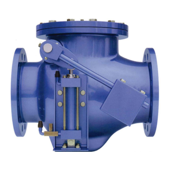
DeZurik APCO CVS-6000 Handbuch für Installation, Betrieb und Wartung - Seite 10
Blättern Sie online oder laden Sie pdf Handbuch für Installation, Betrieb und Wartung für Kontrolleinheit DeZurik APCO CVS-6000 herunter. DeZurik APCO CVS-6000 19 Seiten. Swing check valves
Auch für DeZurik APCO CVS-6000: Handbuch für Installation, Betrieb und Wartung (11 seiten)

DeZURIK
APCO CVS-6000 Swing Check Valves
Start-up Procedure (CVS-6000B Valves)
6. Start pump. While valve is opening, visually verify that Buffer Rod (84) fully extends into the
valve body. If not, pressurize Hydro-pneumatic tank until it does. Table A shows the maximum
stroke length of the Buffer Rod.
Table A:
Maximum Stroke Length of Buffer Rod
Valve Size
Stroke, (inches)
7. Shut-off pump and observe rate of closing.
8. Using the above trial run as a basis, make necessary adjustments on the internal cushion and
Flow Control Valve connected to the hydro-pneumatic accumulator to suit pipeline
requirements. Turning the knob clockwise slows down rate of closure of the disc, and turning it
counterclockwise increases the speed of closing of the valve.
9. Tighten lock nut or set screw under flow control valve knob when final setting is made to prevent
tampering of settings.
Start-up Procedure (CVS-6100 Valves)
1. Position counterweights (29) midway on the lever.
2. Remove pipe plug on top of oil reservoir (58) and install Air Breather, which is shipped with the
valve.
3. Check for proper oil levels. Make sure oil tank is in vertical position. The oil level should be
checked when the valve is closed. Oil should be visible in the elbow, which is the oil fill level.
Add if necessary. (See "Oil Filling Procedure").
4. Open flow control valve (30) three complete turns counter-clockwise from fully closed position.
See "ADJUSTMENT OF FLOW CONTROL VALVE".
5. Turn cushion adjustment screw two complete turn counter-clockwise from fully closed position.
"SEE OPERATION OF INTERNAL CUSHION"
6. Set timing valve cam (47) so that arrow on cam is pointing to the center line of the timing valve
roller while the disc is in closed position. See "TIMING VALVE OPERATION".
7. Start and stop pump and observe rate of closing. Throttle down mainline gate valve (furnished
by others) on discharge side of the Swing Check Valve to approximately 1/2 open to minimize
full column reversal on pump stop.
8. Using the above trial run as a basis, make necessary adjustments to the Timing Valve, Flow
Control Valve and the internal cushion of the cylinder to establish smooth three stage closure.
During this sequence of pump start and stops, gradually open the mainline gate valve
downstream until it is full open.
9. When shut-down sequence is established resulting in a closure of the disc without excessive
pressure surge or slam, lock the Flow Control Valve knob and tighten Timing Valve set screws
to prevent tampering of settings.
D12006
10" 12"
14"
16"
2
2
3
4
Page 10
(Continued)
18"
20"
24"
30"
5
6
4
5
36"
42"
48"
54" 60"
6
7
6
9
December 2012
66"
10
11
