DeZurik APCO CVS-6000 Handbuch für Installation, Betrieb und Wartung - Seite 9
Blättern Sie online oder laden Sie pdf Handbuch für Installation, Betrieb und Wartung für Kontrolleinheit DeZurik APCO CVS-6000 herunter. DeZurik APCO CVS-6000 19 Seiten. Swing check valves
Auch für DeZurik APCO CVS-6000: Handbuch für Installation, Betrieb und Wartung (11 seiten)

Start-up Procedure (CVS-6000 Valves)
Speed Control Adjustment
•
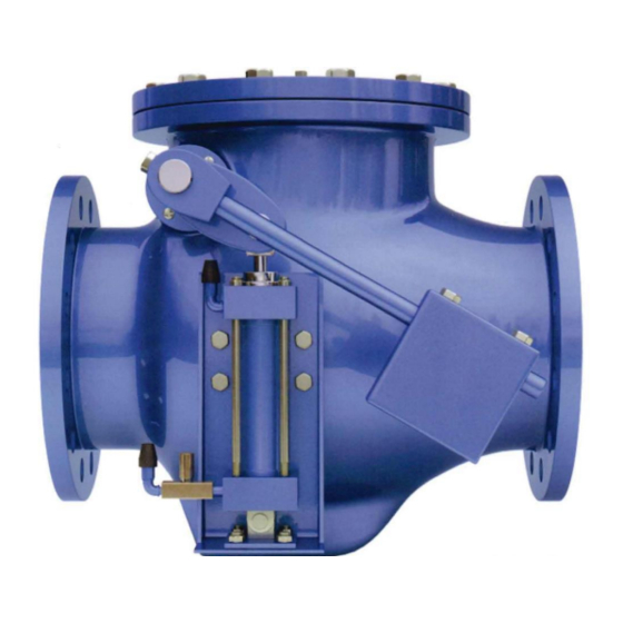
Increase cushioning - Turn adjusting screw of Needle Valve clockwise.
•
Decrease cushioning - Turn adjusting screw of Needle Valve counterclockwise
•
Faster Disc closing - Move Counterweight away from the pivot shaft.
•
Slower Disc closing – Move Counterweight towards pivot shaft.
Condition
Turn adjusting screw of Needle Valve one-half (1/2) turn clockwise. Repeat start
Check valve slams
and stop. If slam persists, continue turning adjusting screw in ½ turn increments.
Be careful not to fully close Needle Valve.
Slam persists
Move weight towards end of lever a couple of inches. Repeat start and stop.
Continue repeating above steps until satisfactory closing is achieved. Then
Slam still persists
increase opening main discharge valve to ½ open. Repeat start and stop pump
sequence and above steps until main discharge valve is full open.
Note: Testing must be conducted carefully and adjustments small increments to arrive at the optimum where the
Swing Check Valve shuts off prior to or at zero reverse flow.
The Series 6000 Swing Check Valve is not a silent closing check valve.
Start-up Procedure (CVS-6000B Valves)
1. Position counterweights (29) midway on the lever.
2. Remove pipe plug on top of oil reservoir (58) and install Air Breather, which is shipped with the
valve.
3. Check for proper oil levels. Make sure oil tanks are in vertical position.
a. Hydro-pneumatic Tank (50): Release air pressure and remove pipe plug on the side of
the tank. Oil should be visible in the elbow, which is the oil fill level. Add if necessary.
(See "Oil Filling Procedure").
b. Oil Reservoir (58): The oil level should be checked when the valve is open. Oil should
be visible in the elbow, which is the oil fill level. Add if necessary. (See "Oil Filling
Procedure")
4. Make initial adjustments to the following speed controls;
Flow Control Valve (C1) = 3 turns open (See "Adjustment of Flow Control Valve")
Flow Control Valve connected to Oil Reservoir = Full open
Internal Cushion Needle Valve = 1-1/2 turns open (See "Operation of Internal Cushion").
5. Pressurize Hydro-pneumatic tank to a pressure according to the formula;
Tank pressure = (Line pressure/4) + 5 psi
This is the pressure necessary to push and extend the buffer rod into the valve body which will
keep it in a position to cushion the closing of the disc when it comes in contact with the buffer
rod.
December 2012
APCO CVS-6000 Swing Check Valves
(Continued)
Adjustment
Page 9
DeZURIK
D12006
