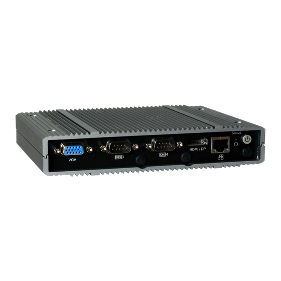
DFI EC700-AL Handbuch zur Schnellinstallation - Seite 2
Blättern Sie online oder laden Sie pdf Handbuch zur Schnellinstallation für Desktop DFI EC700-AL herunter. DFI EC700-AL 4 Seiten.

Removing the Chassis Cover
Before working inside your system, observe the following precautions:
1.
Make sure the system and all other peripherals connected to it have been powered off.
2.
Disconnect all power cords and cables.
3.
The 4 mounting screws on the bottom of the system are used to secure the cover to the
chassis. Remove these screws and put them in a safe place for later use.
Retention Notch
Retention Clip
Installing a SODIMM
The system supports one DDR3L SODIMM socket (plus 2GB/4GB/8GB onboard memory). To
install a memory module, grasp the memory module by its edges and align the module's notch
with the socket's notch; then insert the memory into the socket at an angle and push it down
until you feel a click.
4 5 °
Step 1
Installing a SATA Drive (optional)
The system supports one 2.5" SATA drive depending on the model. Use 4 provided screws to
install a SATA HDD or SSD on the HDD tray. Be sure to insert the SATA cable first before fixing
the HDD on the tray. Then place the HDD tray back into the system and secure the installation
with the provided screws.
Step 2
Step 3
Quick Installation Guide |
Notch
DDR3 SO-DIMM
4 5 °
Key
Socket Top View
Step 1
Step 2
Step 3
Retention Notch
Notch
Retention Clip
Key
Retention Notch
Chassis screw
Retention Clip
DDR3 SO-DIMM
Socket Top View
4 5 °
Step 1
Chassis screw
Step 2
Step 3
Notch
DDR3 SO
Key
Socket T
2
