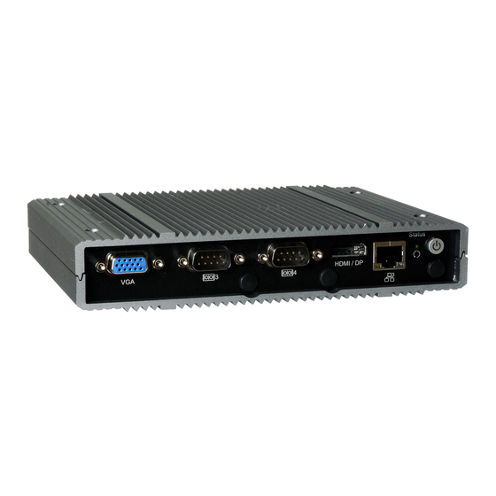
DFI EC700-AL Handbuch zur Schnellinstallation - Seite 3
Blättern Sie online oder laden Sie pdf Handbuch zur Schnellinstallation für Desktop DFI EC700-AL herunter. DFI EC700-AL 4 Seiten.

Installing Mini PCIe, M.2, mSATA and SIM
The system has one M.2 type 2230 socket (E Key), which provides PCIe Gen2 x1 and USB2.0
interfaces and supports the installation of an M.2 22 x 30mm card.
The system board is also equipped with 2 full-size Mini PCIe slot: Mini PCIE2 and mSATA. The
mSATA slot provides SATA interface that accommodates mSATA cards whereas the Mini PCIE2
slot working in conjunction with a Micro SIM slot (on the back side of the board) provides USB 2.0
interface to accommodate common cellular modules.
DC-in (9~36V)
USB 3.0
Front
Panel
5
1
6
2
Buzzer
Mini PCIe Module
JP7
Auto power-on: reserved
1
Battery
Notch
auto-detect
Status
LED
To install a Mini PCIe or an M.2 card:
1.
Grasp the Mini PCIe card by its edges and align the notch of the card with the key in the
connector and insert the bottom edge of the card into the connector.
2.
Push down on the other end of the card and use the provided mounting screw to secure the
card on the system board.
To install a micro SIM card:
Remove the screw and the standoffs that fix the system board to the chassis. Then detach the
board from the chassis.
LAN 1
LAN 4
LAN 2
Mini PCIe Module
Notch
Mini PCIe Socket
Stand-off
Key
DP/HDMI
COM 4
COM 1
LAN 1
Intel
WGI210IT
Stand-off
DDR3L
DDR3L
SPI ROM
COM 3
Mini PCIe Module
Notch
1
Mini PCIe Socket
JP13
SATA
Power
Key
SATA 1
SATA 3.0
Front
Audio
VGA
Mini PCIe Soc
Stand-off
Key
M.2 Slot
Mini PCIe Slots
3
