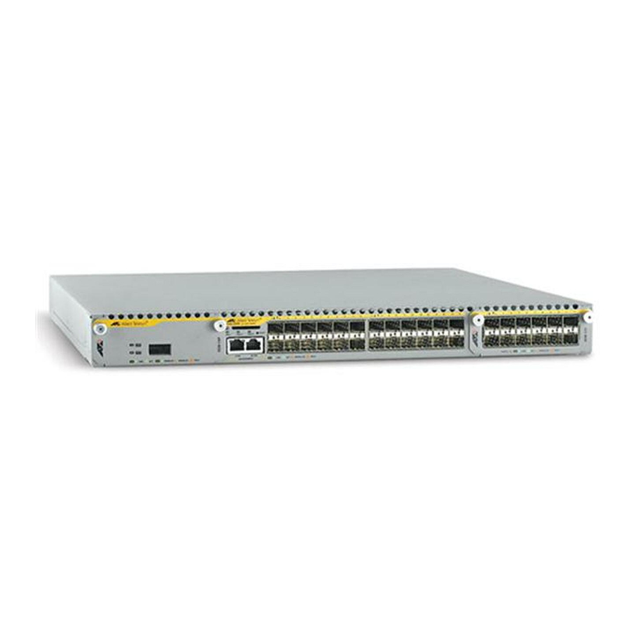
Allied Telesis x900 Series Installationshandbuch - Seite 4
Blättern Sie online oder laden Sie pdf Installationshandbuch für Schalter Allied Telesis x900 Series herunter. Allied Telesis x900 Series 13 Seiten. Removable power supply and fan
Auch für Allied Telesis x900 Series: So konfigurieren Sie (9 seiten)

Removable Power Supply and Fan
Models Covered by this Guide
This document describes how to install the following models:
■
AT-PWR01 PSU, either AC or DC power supply unit
■
AT-PWR02 PSU, AC power supply unit only
■
AT-FAN01, fan-only module
Compatible Switches
The following table shows which models of PSUs and FOMs are appropriate for
individual switches.
Switch
AT-8948 and x900-48FE
AT-9924T, AT-9924SP, AT-9924T/4SP
AT-9924Ts and x900-24X
Package Contents
Each switch is supplied with a single power supply unit (PSU), either AC or DC.
Depending on the model, the switch also has a fan-only module (FOM) or a
blanking panel.
■
The AT-8948, AT-9924Ts, x900-24X, and AT-9924T/4SP switches have a
PSU and a FOM installed.
■
The x900-48FE, AT-9924T, and AT-9924SP switches have a PSU and a
blanking panel installed.
The following items are included with each factory-installed PSU. Contact your
authorised distributor or reseller if any are damaged or missing.
■
one AC power cord (AC model)
■
one power cord retaining clip (AC model)
■
one warranty card
4
PWR01
PWR02
!
!
!
!
!
FAN01
!
!
!
