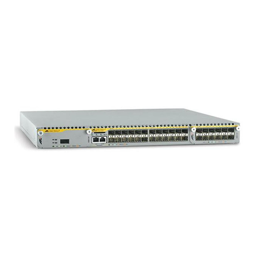
Allied Telesis x900 Series Installatiehandleiding - Pagina 4
Blader online of download pdf Installatiehandleiding voor {categorie_naam} Allied Telesis x900 Series. Allied Telesis x900 Series 13 pagina's. Removable power supply and fan
Ook voor Allied Telesis x900 Series: Hoe configureren (9 pagina's)

Removable Power Supply and Fan
Models Covered by this Guide
This document describes how to install the following models:
■
AT-PWR01 PSU, either AC or DC power supply unit
■
AT-PWR02 PSU, AC power supply unit only
■
AT-FAN01, fan-only module
Compatible Switches
The following table shows which models of PSUs and FOMs are appropriate for
individual switches.
Switch
AT-8948 and x900-48FE
AT-9924T, AT-9924SP, AT-9924T/4SP
AT-9924Ts and x900-24X
Package Contents
Each switch is supplied with a single power supply unit (PSU), either AC or DC.
Depending on the model, the switch also has a fan-only module (FOM) or a
blanking panel.
■
The AT-8948, AT-9924Ts, x900-24X, and AT-9924T/4SP switches have a
PSU and a FOM installed.
■
The x900-48FE, AT-9924T, and AT-9924SP switches have a PSU and a
blanking panel installed.
The following items are included with each factory-installed PSU. Contact your
authorised distributor or reseller if any are damaged or missing.
■
one AC power cord (AC model)
■
one power cord retaining clip (AC model)
■
one warranty card
4
PWR01
PWR02
!
!
!
!
!
FAN01
!
!
!
