Miele KM 400 Installationsanleitung Handbuch - Seite 11

Blättern Sie online oder laden Sie pdf Installationsanleitung Handbuch für Kochfeld Miele KM 400 herunter. Miele KM 400 20 Seiten. Ceramic hobs; ceramic contact grill; open grill; deep fat fryer
Auch für Miele KM 400: Betriebsanleitung (24 seiten), Installationsanleitung Handbuch (16 seiten), Produkt- und Ausschnittabmessungen (1 seiten), Betriebsanleitung (28 seiten), Installationsanleitung Handbuch (20 seiten), Betriebsanleitung (24 seiten), Installationsanleitung Handbuch (16 seiten)
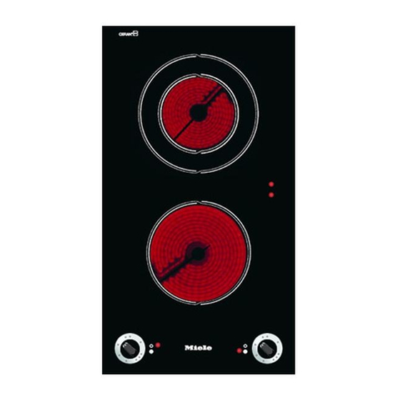
Miele KM 400 Installationsanleitung Handbuch
Dimensions 7 mm and 11 mm are the
space taken up by the frame of the
appliance on the worktop.
^ Make a cut-out for the hob in the
worktop, paying attention to the
appliance height. See section
"Appliance dimensions".
Dimension "B" applies to a combination
of appliances and is shown on the
chart.
There must be a minimum safety
distance of 50 mm between the
appliance and the back wall and the
following distances from a side wall to
the right or left of the appliance:
KM 400, KM 402, KM 403, KM 412
KM 418 = 40 mm
KM 408-1 = 50 mm
KM 410 / KM 411 = 250 mm
See also chapter "Warning and Safety
Instructions".
^ Seal the cut surfaces with a suitable
sealant to avoid swelling caused by
moisture.
The materials used must be heat
resistant.

Worktop cut-out

Installing one or more appliances
Cut out the worktop according to the
dimensions listed in the following chart.
Number of
appliances
± 1 mm
1
2
3
4
5
6
7
Important:
The maximum tolerance for the worktop
cut-out must not exceed ± 1 mm.
When building in several combiset
appliances a spacer bar must be
fitted between each unit.
See chapter "Fitting the spacer bars
and spring clamps".
Worktop cut-out
Depth
Width
(= Dim. B)
in mm
in mm
± 1 mm
500
266
500
554
500
842
500
1130
500
1418
500
1706
500
1994
11