Miele KM 400 Manuel d'instructions d'installation - Page 11

Parcourez en ligne ou téléchargez le pdf Manuel d'instructions d'installation pour {nom_de_la_catégorie} Miele KM 400. Miele KM 400 20 pages. Ceramic hobs; ceramic contact grill; open grill; deep fat fryer
Également pour Miele KM 400 : Manuel d'utilisation (24 pages), Manuel d'instructions d'installation (16 pages), Dimensions du produit et de la découpe (1 pages), Manuel d'utilisation (28 pages), Manuel d'instructions d'installation (20 pages), Manuel d'utilisation (24 pages), Manuel d'instructions d'installation (16 pages)
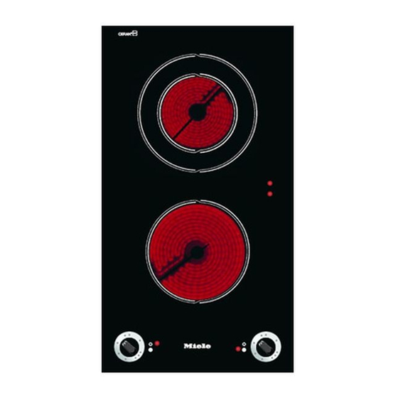
Miele KM 400 Manuel d'instructions d'installation
Dimensions 7 mm and 11 mm are the
space taken up by the frame of the
appliance on the worktop.
^ Make a cut-out for the hob in the
worktop, paying attention to the
appliance height. See section
"Appliance dimensions".
Dimension "B" applies to a combination
of appliances and is shown on the
chart.
There must be a minimum safety
distance of 50 mm between the
appliance and the back wall and the
following distances from a side wall to
the right or left of the appliance:
KM 400, KM 402, KM 403, KM 412
KM 418 = 40 mm
KM 408-1 = 50 mm
KM 410 / KM 411 = 250 mm
See also chapter "Warning and Safety
Instructions".
^ Seal the cut surfaces with a suitable
sealant to avoid swelling caused by
moisture.
The materials used must be heat
resistant.

Worktop cut-out

Installing one or more appliances
Cut out the worktop according to the
dimensions listed in the following chart.
Number of
appliances
± 1 mm
1
2
3
4
5
6
7
Important:
The maximum tolerance for the worktop
cut-out must not exceed ± 1 mm.
When building in several combiset
appliances a spacer bar must be
fitted between each unit.
See chapter "Fitting the spacer bars
and spring clamps".
Worktop cut-out
Depth
Width
(= Dim. B)
in mm
in mm
± 1 mm
500
266
500
554
500
842
500
1130
500
1418
500
1706
500
1994
11