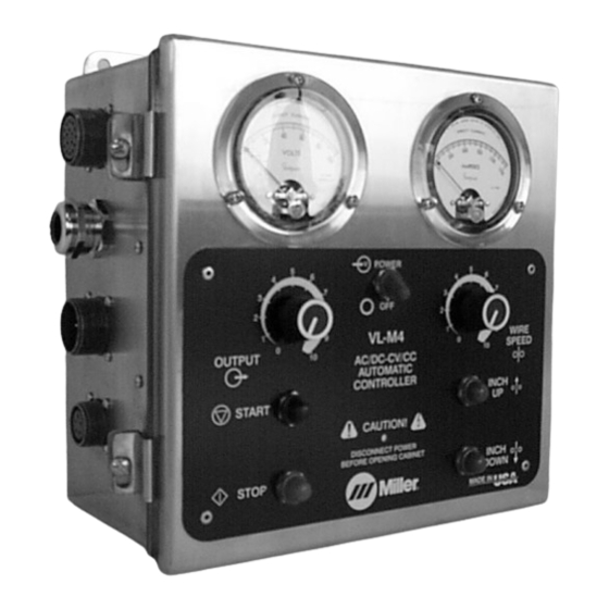
Miller VL-M4 Benutzerhandbuch - Seite 18
Blättern Sie online oder laden Sie pdf Benutzerhandbuch für Zubehör für das Schweißen Miller VL-M4 herunter. Miller VL-M4 36 Seiten. Submerged arc controller for automatic welding

4-4. Connecting Shunt Control
1
4-5. Left Side Panel Connections
1
2
A
B
M
C
L
N
P
T
K
D
R
S
J
E
H
G
F
Example Receptacle
OM-189 530 Page 14
4
2
3
3
4
5
6
YTurn Off welding power
source and weld control.
Select and prepare proper size and
length weld cables according to the
welding power source Owner's
Manual. Remove cover from shunt
control.
1
17-Pin Receptacle
2
Shunt
3
Bus Bar On Shunt
4
Bus Bar On Shunt
Route and connect a weld cable
from selected weld output terminal
on welding power source to one
bus bar on shunt (see Section 4-3).
Route and connect another weld
cable from remaining bus bar on
shunt to wire drive assembly (see
Section 4-3).
Reinstall cover onto shunt control.
Ref. ST-083 353-C
1
Receptacle
2
Keyway
3
17-Pin Receptacle:
Connection to Shunt Control
4
For Customer Use:
Connections To Terminal
Strips, Flux Valve, etc.
Route incoming cables through
this strain relief prior to making
connections to internal terminal
strips.
5
14-Pin Receptacle:
Connection To Welding
Power Source.
6
5-Pin Receptacle:
Connection to Wire Drive
Motor
To connect matching interconnect-
ing cord to one of the above
receptacles, align keyway, insert
plug, and tighten threaded collar.
Connect remaining end of cord to
matching receptacle on applicable
equipment.
Ref. 802 531
