Burkhard Reuter RLA4 Spezifikationen und Betriebsanleitung - Seite 4
Blättern Sie online oder laden Sie pdf Spezifikationen und Betriebsanleitung für Antenna Burkhard Reuter RLA4 herunter. Burkhard Reuter RLA4 9 Seiten.
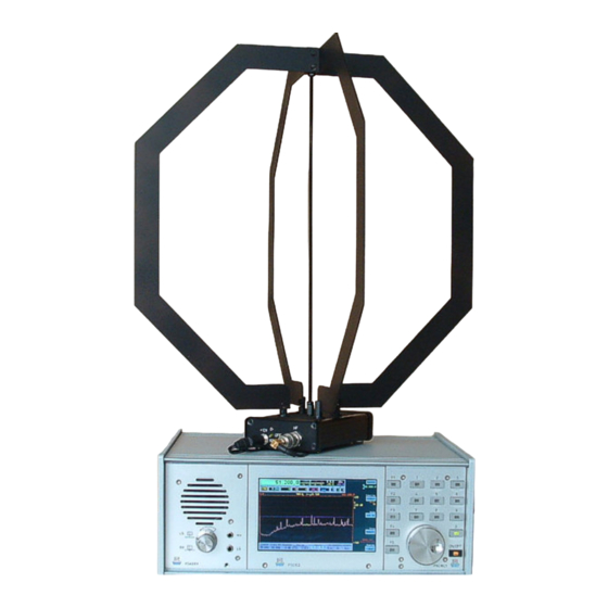
The RLA4 is a small loop receiving antenna for indoor or portable outdoor use. It operates broadband as
an untuned active antenna with integrated amplifier. The antenna can be powered via the RF cable or a
DC socket directly on the amplifier. The receiver element consists of 2 etched copper loops on FR4 board
material for symmetrical feed of two differential current amplifiers with very low impedance input. The use
of the latest components within the two amplifier branches guarantees low intrinsic noise values and high
intermodulation resistance. The two receiving loops are arranged at an angle of 90° to each other. They
can be switched by switching the respective amplifier on or off.
The RLA4 also provides fine-step control of the amplifier to achieve electronic rotation of the receiving
direction. In versions 4A to 4C, the amplifier can be switched to high-impedance input asymmetrical to
ground. The entire loop design then no longer operates as a loop ("magnetic") antenna but as a "whip"
antenna for omnidirectional reception of the electric field component.
The amplifier operates within an anodized aluminum profile housing. The connection to the RX is made via
a BNC socket. A DC socket is available for local supply (for usual plugs of universal power supply units).
The positive pole lies on the pin (2.5 mm). Power can also be supplied via the RF cable (remote supply).
To feed the DC voltage into the cable, a bias tee is required (not included in delivery) or a receiver with the
ability to feed preamplifiers directly from the receiver input.
Up to version 4C, the antenna is switched on by a lighted toggle switch and switched over in receiving
mode (magnetic "loop" / electrical "whip").
When operating the RLA4 via the normal circuit as a loop, the loop is active from the front right (via jack
"RX") to the rear left. Its main reception direction lies in this direction (in the loop plane, corresponds to 0°).
To change the receiving direction, the antenna must be rotated. This can be done mechanically by turning
the housing together with the loop construction, or electronically by using the control unit for the RLA4 (see
separate description). In loop mode, the receiving loops are grounded by the rod in the middle.
As a result, and due to the generally low noise sensitivity of loop antennas, a good suppression of local
interferences (emissions from PC, TV, switching power supplies, cabling, etc.) is achieved. In addition, the
performance of the antenna is relatively independent of the operating site. It requires neither a particularly
increased position, nor special grounding wires or the like (however, overvoltage protection must be
observed!).
When operated as a whip, the entire construction including the center rod is electrically separated from the
chassis ground ("ground-plane"). In addition, due to the now high-impedance circuit of the amplifier
(almost) no current flows in the loops. Instead, the potential difference of the loop construction is
measured against earth. It thus acts as a probe for the electric field component of the received EM field.
EDITION
DATE
1.5
8/19/19
Operator's Manual
The RLA4A-C's connectors and switches
K & M Burkhard Reuter
NAME
RLA4
B. Reuter
4
9
Page
of