Chromalox RTPC Einbauanleitung - Seite 3
Blättern Sie online oder laden Sie pdf Einbauanleitung für Kabel und Anschlüsse Chromalox RTPC herunter. Chromalox RTPC 4 Seiten. Power connection kit for self-regulating & constant wattage heating cables
Auch für Chromalox RTPC: Installationsanleitung Handbuch (8 seiten)
7. FOR ALL CABLES:
Feed the cables through the corresponding holes in the box.
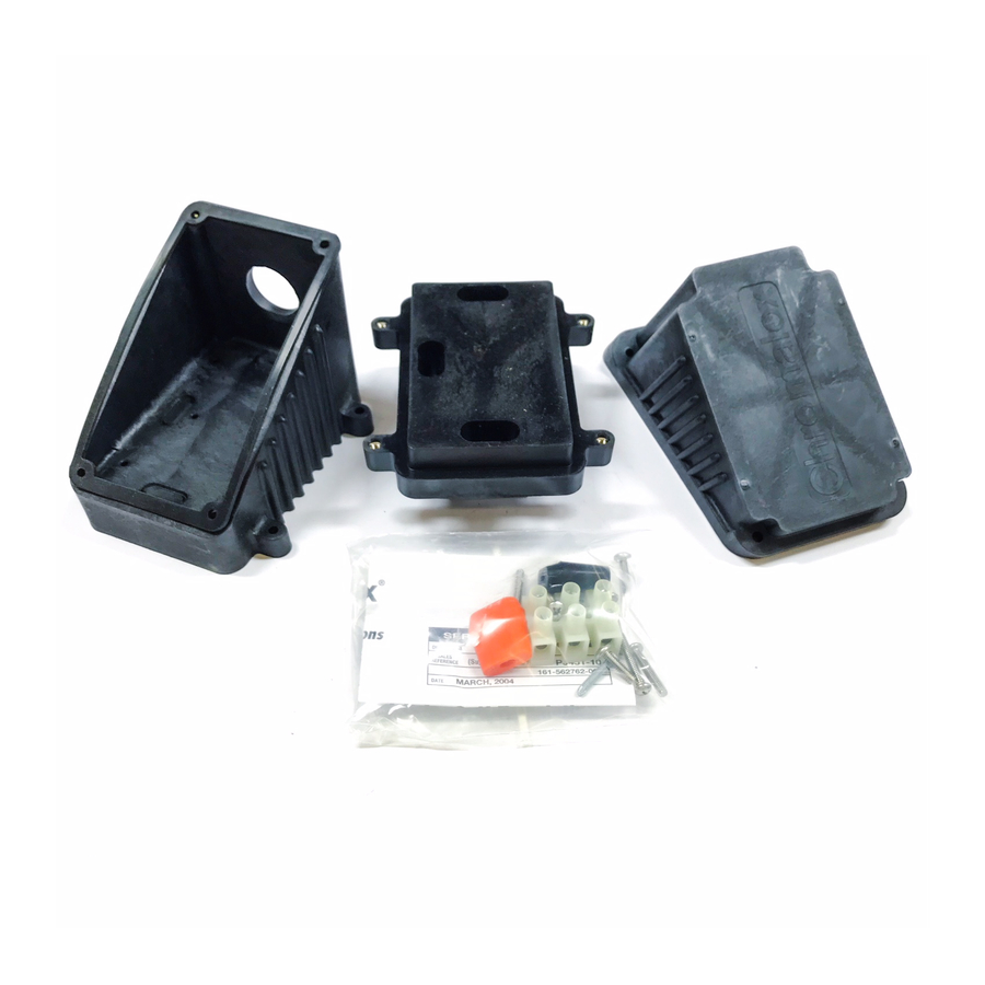
Secure box to base using all four (8-32) screws. See Figure 7.
#8/32 Screw
8. FOR OVERCOATED CABLES:
Starting from the end of the cable, unravel 2-1/2 inches of the
braid. Twist the strands together to form a pigtail. See Figure 8.
2-1/2"
9. FOR SELF-REGULATING CABLES:
Using standard electrical cutters, cut a 3/4 inch long notch out
of the cable between the conductor wires. Bare a 3/8 inch
length of each conductor by stripping off the outside insula-
tion and the inner black core material. See Figure 9.
3/8"
3/4"
10. FOR CONSTANT WATTAGE CABLES:
Score the outer jacket 3/4 inch from the end of the cable and
remove the jacket. Cut off the exposed nichrome wire, push-
ing any remainder back under the jacket. These cables have an
inner layer of insulation which is also to be removed as
INSTALLATION
Figure 7
Figure 8
Figure 9
described above. Separate the buss wires and strip off the last
3/8 inch of insulation from both buss wires. See Figure 10.
3/4"
Figure 10
11. FOR ALL CABLES:
Insert the bared ends of the conductors into the openings in
the terminal block. Tighten screws firmly to hold conductors
in place. See Figure 11.
Figure 11
12. FOR OVERCOATED CABLES (-CR or -CT):
Insert the end of the braid pigtail into the remaining opening
in the terminal block. Tighten screw firmly to hold the braid in
place. See Figure 12.
Figure 12
13. FOR ALL CABLES:
Connect conduit hub (Chromalox CCH or equal) to the box.
Attach conduit to hub and bring power leads into box. See
Figure 13.
Figure 13
3/8"