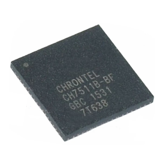
Chrontel CH7511B Design-Handbuch - Seite 2
Blättern Sie online oder laden Sie pdf Design-Handbuch für Empfänger Chrontel CH7511B herunter. Chrontel CH7511B 16 Seiten. Edp/dp receiver

CHRONTEL
2.1.2 Power Supply Pins
There are eleven power supply pins: AVDD, DVDD, LVDD, and VDDGPO. Refer to Table 1 for the Power supply
pin assignments. Refer to Figure 1 for Power Supply Decoupling.
Table 1: Power Supply Pin Assignments for the CH7511B/7512B (68QFN)
Pin
7,42
3,4,60,66,67
18,32,52
8,21,35,40,45,63,
Thermal pad
U1
The rmal P ad
QFN
CH 7511B
2
# of Pins
Type
Symbol
2
Power
DVDD
5
Power
AVDD
3
Power
LVDD
6
Ground
GND
3,4 ,60,66 ,67
AVD D
C1
C2
0.1 uF
0.1 uF
8,2 1,35,4 0,45,6 3
GN D
7,4 2
0.1 uF
DV DD
C10
C11
18, 32,52
0.1 uF
0.1 uF
LVD D
T1
VCC33
VCC18
RESETB
Figure 1: Power Supply Decoupling and Distribution
Description
Digital supply voltage (1.8V)
Analog supply voltage (1.8V)
LVDS driver supply voltage and GPIO
supply voltage (3.3V)
Power ground
47R 100MHz
L1
1
C6
C3
C4
C5
0.1 uF
0.1 uF
0.1 uF
10u F
47R 100MHz
C7
C8
C9
L2
1
0.1 uF
10u F
47R 100MHz
C12
C13
L3
1
0.1 uF
10u F
206-1000-014
AN-B014
2
VC C1_8
2
VC C3_3
2
Rev. 1.7
2020-07-14
