HP ProCurve 1600M Installationshandbuch - Seite 20

Blättern Sie online oder laden Sie pdf Installationshandbuch für Schalter HP ProCurve 1600M herunter. HP ProCurve 1600M 28 Seiten. Redundant power supply
Auch für HP ProCurve 1600M: Spezifikationsblatt (12 seiten), Lies mich zuerst (8 seiten), Handbuch für Rezensenten (27 seiten), Ergänzendes Handbuch (2 seiten), Ergänzendes Handbuch (2 seiten), Installationshandbuch (28 seiten), Installationshandbuch (36 seiten), Handbuch zur Schnelleinrichtung (2 seiten), Handbuch zur Schnelleinrichtung (4 seiten), Benutzerhandbuch (8 seiten), Handbuch Ergänzung (28 seiten), Lies mich zuerst (16 seiten), Montage und Demontage (2 seiten), Installationshandbuch (12 seiten), Handbuch für Planung und Durchführung (40 seiten), Anweisungen zur Demontage des Produkts nach Ablauf der Lebensdauer (2 seiten), Installationshandbuch (46 seiten), Diagnostik-Handbuch (2 seiten), Anweisungen für die Demontage (2 seiten)
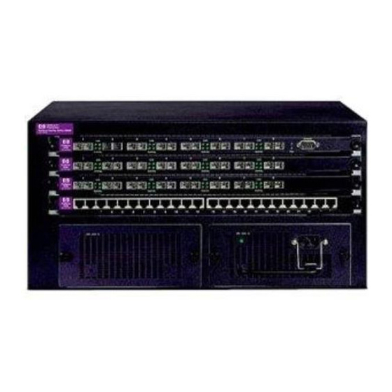
HP ProCurve 1600M Installationshandbuch
Troubleshooting
Tip
Number
Problem
The module was
installed in the
slot after a
different type
module was
previously
installed, and the
switch has not
yet been reset.
The module has
experienced a
self test fault.
The module or
one of the
transceivers has
experienced a
self test fault.
14
When you "hot swap" modules in the switch slot, if you install a different module type
than the one that was previously installed in the slot, you must reset the switch so the
switch processor can properly initialize and configure the new module type. The
flashing LED informs you that this change of module types has occurred. The module
will not work properly until the switch is reset as indicated by all the module's LEDs
staying on until the switch is reset.
See "Reset the Switch" on page 10.
The module and transceivers are tested whenever the switch is powered on, or reset
(through the Reset button on the switch, or the Reboot or Reset options in the console
or web browser interface). When the module is hot swapped (installed when the switch
is powered on), the self test is a partial test that may not detect all possible module
failures and does not detect transceiver failures.
Try the following procedures to resolve this condition:
• Remove and reinstall the module. You can do this without having to power down the
switch. When the module is reinstalled, it will be retested automatically.
• If this does not resolve the condition, try resetting the switch. See "Reset the
Switch" on page 10. A more thorough test is performed when the switch is reset or
power cycled.
If the same fault indication reoccurs or a new fault indication results from the switch
reset, see tip
below.
The self test that is performed after the switch is powered on or reset is a complete
test of both the module and the transceivers.
If ONE set of module port LEDs (Link and Mode LEDs for one of the ports) stays on, the
faulty unit is probably the transceiver associated with the LEDs that are on. Try these
procedures:
1. Remove the module from the switch.
2. Remove the suspected transceiver from the module.
3. Reinstall the module and reset the switch. See "Reset the Switch" on page 10.
• If the self test is successful, the transceiver is faulty and must be replaced.
• If the self test still fails, the module is faulty and must be replaced.
If both sets of port LEDs stay on, the faulty unit is probably the module. Try these
procedures:
1. Remove the module from the switch.
2. Remove both of the transceivers.
3. Reinstall the module and reset the switch.
• If the self test is successful, both of the transceivers are faulty and must be
replaced.
• If the self test still fails, the module is faulty and must be replaced.
Solution