Grasp the knurled portion of the knurled outer barrel
with soft-jaw pliers to hold it stationary, and use a
suitable slotted screwdriver to tighten the slotted end-
screw (see
Figure
34).
Figure 34 – Grip the knurling and tighten the end-screw
This completes the overhaul of the BHS/BHT viewing
head locking thumbscrew.
locking screw is now ready to provide many more years
of trouble-free service (see
Figure 35 – Locking thumbscrew is ready for use
Servicing Viewing Head Locking Screw (BHSU/BHTU)
To restore proper freedom of motion to a stiff
BHSU/BHTU
locking
thumbscrew must be removed from the pillar arm so
that any thick or hardened grease or contaminants can
be removed from the threads, and then reinstalled into
the pillar arm with fresh grease.
Remove the Locking Thumbscrew (BHSU/BHTU)
Place a suitable dust-free cloth or lens tissue over the
exposed optics in the dovetail recess for the viewing
head (see
Figure
36) and place a piece of cardboard
over this cloth or tissue, to fully protect the exposed
optical element from debris and damage during
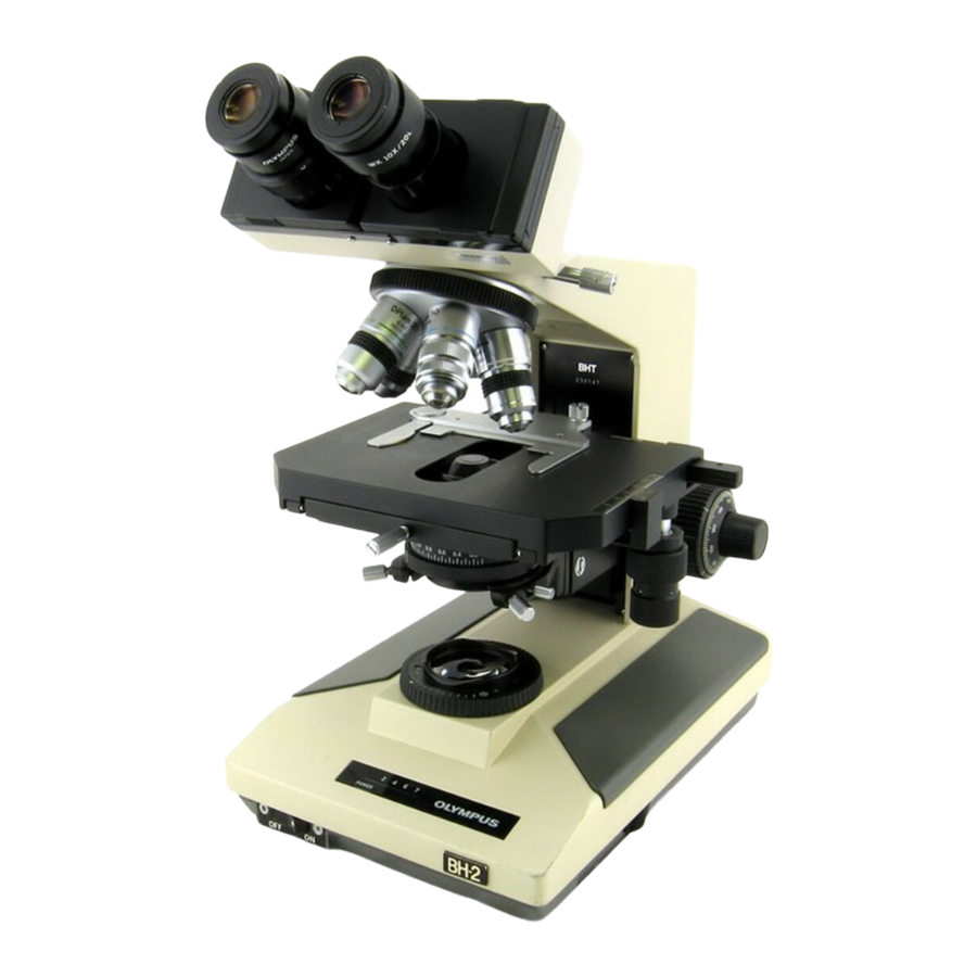
Teardown, Cleaning, and Reassembly of the Miscellaneous Parts of the Olympus BH-2 Microscope Frames
The newly refurbished
Figure
35).
thumbscrew,
the
locking
removal and reinstallation of the viewing head locking
thumbscrew (see
Figure
Figure 36 – Protect the exposed optics with tissue
Figure 37 – Protect the exposed optics with cardboard
Use a needle nose pliers to carefully grasp and remove
the e-clip from the groove in the end of viewing head
locking thumbscrew (see
Figure 38 – Remove e-clip from the end of thumbscrew
37).
Figure
38).
Revision 1
Page 15 of 45