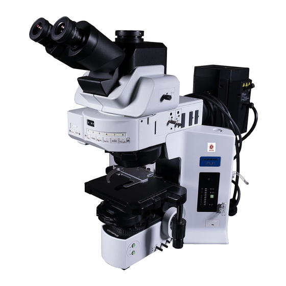
Olympus BX61 Anleitung Handbuch - Seite 18
Blättern Sie online oder laden Sie pdf Anleitung Handbuch für Mikroskop Olympus BX61 herunter. Olympus BX61 40 Seiten. Motorized system microscopes

²
|
³
@
@
14
Fig. 20
Fig. 21
2
Adjusting the X/Y-Axis Knob Tension
1. Hold the X-axis knob @ and slide up the Y-axis knob ² up to expose the
adjustment knobs.
2. Turning the X-axis adjustment knob ³ or Y-axis adjustment knob | clock-
wise (in the direction of the arrow) increases the rotation tension and
counterclockwise decreases it.
# If the tension is adjusted too tight, a creaking sound may be heard
during stage travel, and the stage stopping accuracy may be imper-
iled.
After long hours of use, the stage guide may be devi-
CAUTION
ated and the stage travel range may be decreased.
However, this is not malfunction and can be corrected
easily as described below.
[Treatment] X-axis direction: Hold the specimen holder and move the
Y-axis direction: Hold the upper stage and move it to the front
Rubber Stage Knob Caps (Optional)
}When the X/Y-axis knobs are fitted with the rubber caps, the knobs can
be adjusted without slipping and fine adjustment is possible by holding
the knobs with a very light force. The knob rubber caps also reduce
fatigue after long hours of operation.
The U-SHGT thick type (thickness 5 mm) and U-SHG thin type (thickness
2 mm) knob rubber caps are available.
To attach the knob rubber caps:
First fit the larger rubber knob cap to the Y-axis (upper) knob from below
it, then fit the smaller rubber knob cap to the X-axis (lower) knob from
below it.
3
Rotating the Stage
1. Slightly loosen the stage clamping knob @.
2. The stage can be rotated both clockwise and counterclockwise while
holding the stage clamping knob.
# A click may be heard and felt during rotation. However, this is due to
the construction of the substage and does not indicate a malfunc-
tion.
}The angle of rotation varies depending on the positions of the feed knobs.
Right-hand knobs
Left-hand knobs
stage guide to the left and right so that it hits
the stoppers.
and rear so that it hits the stoppers.
Angle of Rotation
Clockwise
Counterclockwise
230°
20°
(Fig. 20)
(Fig. 21)
20°
230°
