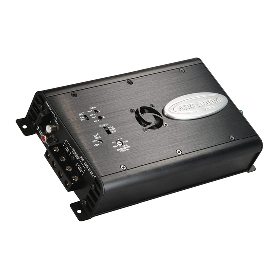
ARC Audio KS125.2 MINI Installationsanleitung Handbuch - Seite 10
Blättern Sie online oder laden Sie pdf Installationsanleitung Handbuch für Verstärken ARC Audio KS125.2 MINI herunter. ARC Audio KS125.2 MINI 17 Seiten. Moto series

........ Continued
C. After you have removed all of the hardware
carefully, while supporting the main fairing cover,
remove the remaining center t25 bolt that you had
previously reinstalled at the windshield mounting
bracket and remove the front fai]ing and place aside
in a safe place.
Step 5-
Mounting and wiring the amplifier
A. Using the provided adhesive backed velcro place
the large section of velcro onto the bottom of the
amplifier. If your motorcycle is equipped with the
onboard PA/CB system unscrew the main housing by
removing the single bolt located on the back of the
radio. (See Figure 5A)
B.Then using a residue free cleaner prepare the sur-
face of the top of the radio by cleaning it thoroughly
(See Figure 5B). Then place the amplifier onto the top
of the radio and press firmly to ensure proper adhe-
sion of the velcro to both surfaces.(See Figure 5C).
Be sure to push the radio as far foward toward the
gauges as possible to ensure proper fit.
C. Next pull the remainder of the main harness thru
the opening in the center of the fairing (See Figure
5D) next to the motorcycles main wire harness. Then
secure the main harness to the motorcycles factory
wiring with wire zip ties (Provided)
D. After pulling the main power harness into the
fairing route your wires carefully to the amplifier.
Once routed secure the harness to the motorcycles
factory wiring and then attach the harnesses power and
ground to the amplifier. (See Figure 5E)
E. Next take the black hi level input grounding lead
on the 5 pin input harness and connect it to the
ground wire plug on the bikes cigarette lighter. (See
Figure 5F) or you may connect it to the T15 Torx
located at the top of the abck of the radio chassis if
you have an crimp style eye loop connector available.
F. Next retrieve the orange turn one lead with termi-
nation on one end (Provided in wire kit and attach to
the amplifier in the approperiate terminal.
G. Once secured to the amplifier route the turn on
lead to the fairings front headlight harness. There
you will find an unused and terminated wire which is
accessory switched 12 volts(Orange w/white stripe).
Attach the provided turn on lead to this wire. (See
Figure 5H)
Figure 5A-
Figure 5B-
Figure 5C-
Figure 5D-
Figure 5E-
Figure 5F-
Figure 5G-
