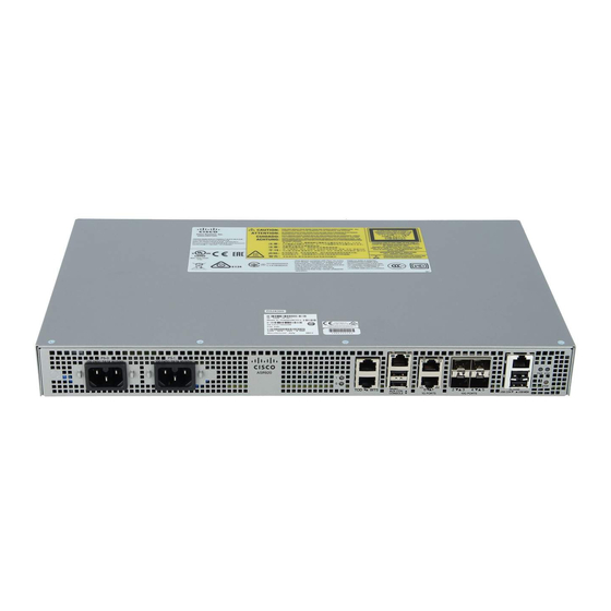
Cisco ASR 920 series Handbuch zur Installation - Seite 24
Blättern Sie online oder laden Sie pdf Handbuch zur Installation für Schalter Cisco ASR 920 series herunter. Cisco ASR 920 series 42 Seiten. Aggregation services router
Auch für Cisco ASR 920 series: Handbuch zur Installation (36 seiten), Erste Schritte (6 seiten), Hardware-Installationshandbuch (46 seiten), Handbuch (36 seiten)

Connect to SFP Modules
• Let the ports autonegotiate both speed and duplex.
• Set the port speed and duplex parameters on both ends of the connection.
SUMMARY STEPS
1. When connecting to workstations, servers, and routers, connect a straight-through cable to an RJ-45
connector on the front panel.When connecting to routers or repeaters, use a crossover cable.
2. Connect the other end of the cable to an RJ-45 connector on the other device. The port LED turns on when
both the router and the connected device have established link.
3. Reconfigure and reboot the connected device, if necessary.
4. Repeat Steps 1 through 3 to connect each device.
DETAILED STEPS
Step 1
When connecting to workstations, servers, and routers, connect a straight-through cable to an RJ-45 connector on the
front panel.When connecting to routers or repeaters, use a crossover cable.
Note
You can use the mdix auto interface configuration command in the CLI to enable the automatic
medium-dependent interface crossover (auto-MDIX) feature. When the auto-MDIX feature is enabled, the router
detects the required cable type for copper Ethernet connections and configures the interfaces accordingly.
Therefore, you can use either a crossover or a straight-through cable for connections to a copper 10/100/1000,
or an SFP module port on the router, regardless of the type of device on the other end of the connection.
Step 2
Connect the other end of the cable to an RJ-45 connector on the other device. The port LED turns on when both the
router and the connected device have established link.
If the port LED does not turn on, the device at the other end might not be turned on, or there might be a cable problem
or a problem with the adapter installed in the attached device.
On user network interface (UNI) ports, the port LED is green after the link is established.
Note
Step 3
Reconfigure and reboot the connected device, if necessary.
Step 4
Repeat Steps 1 through 3 to connect each device.
Connect to SFP Modules
This section describes how to connect to SFP modules. For instructions on how to connect to fiber-optic SFP
modules, see the Connecting to Fiber-Optic SFP Modules, page 3-20 .
For instructions about how to install or remove an SFP module, see the Installing and Removing SFP Modules,
page 3-16 .
Connect to Fiber-Optic SFP Modules
Follow these steps to connect a fiber-optic cable to an SFP module:
Class 1 laser product. Statement 1008
Warning
Cisco ASR 920 Series Aggregation Services Router Hardware Installation Guide
24
Installing the Cisco ASR 920 Series Router
