Crestron 4K DigitalMedia DMPS3-4K-150-C Aus dem Handbuch
Blättern Sie online oder laden Sie pdf Aus dem Handbuch für Konferenz-System Crestron 4K DigitalMedia DMPS3-4K-150-C herunter. Crestron 4K DigitalMedia DMPS3-4K-150-C 2 Seiten. 3-series digitalmedia presentation system 150
Auch für Crestron 4K DigitalMedia DMPS3-4K-150-C: Ergänzendes Handbuch (20 seiten), Handbuch (2 seiten), Aus dem Handbuch (2 seiten)
DO
GUIDE
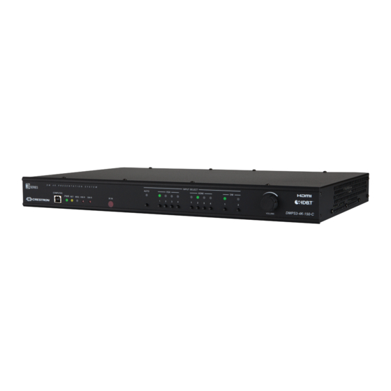
DMPS3-4K-150-C
3-Series
4K DigitalMedia
Presentation System 150
®
TM
DO
Install the Device
The DMPS3-4K-150-C can be mounted into a rack, mounted under a table,
or placed onto a fl at surface.
Mounting into a Rack
The DMPS3-4K-150-C occupies 1U of rack space. Using a #1 or #2 Phillips
screwdriver, attach the two included rack ears to the device. Then, mount
the device into the rack using four mounting screws (not included).
Mounting under a Table
Using a #1 or #2 Phillips screwdriver, attach the four included table mount
brackets to the device. Then, attach the four table mount brackets to the
underside of the table using four mounting screws (not included).
Placing onto a Flat Surface
When placing the device onto a fl at surface or stacking it with other
equipment, attach the included feet near the corners on the underside of
the device.
DO
Make Connections to the Rear Panel
Make connections to the rear panel of the DMPS3-4K-150-C as follows:
VGA IN 1–4: Connect to RGB (VGA), component, S-video, or composite
video sources.
AUDIO IN 1–4: Connect to unbalanced audio sources.
HDMI IN 1–4: Connect to HDMI
audio/video sources.
®
DM IN 1–2: Connect to the DM 8G+™ output of DigitalMedia™
transmitters or other DigitalMedia devices or to third-party HDBaseT
devices.
1
HDMI OUT: Connect to the display.
DM OUT: Connect to the DM 8G+ input of a DigitalMedia receiver or other
DigitalMedia device or to a third-party HDBaseT device.
1
RELAY 1–2: Connect to controllable devices.
INPUT: Connect to a digital or analog output device.
AUDIO OUT: Connect to the receiving device using the supplied 5-pin
interface connector.
IR OUT: Connect to the included Crestron
STIRP IR emitter probe.
®
MIC IN: Connect to a microphone.
COM: Connect to the device to be controlled using the included 5-pin
interface connector.
LAN: Connect to the local area network.
USB 1–4 (Type A): Connect to the USB port of TT-100 Series presentation
interfaces.
G: Connect to earth ground (building steel).
NET: Connect to the 4-pin NET port of a Cresnet
device using the
®
included 4-pin interface connector.
100–240V~1.4A 50/60 Hz: Connect to a 120 V power outlet using the
included power cord.
DO
Check the Box
QUANTITY
PRODUCT
2
Bracket, Rack Ear, 1U
4
Bracket, Under Table Mount
2
Connector, 3-Pin
2
Connector, 4-Pin
2
Connector, 5-Pin
1
Emitter Probe, IR, Crestron STIRP
4
Foot, 0.5" x 0.5" x 0.23", Adhesive
1
Power Cord, 6' 7" (2 m)
Not Included: Cables, Rack Mount Screws, and Table Mount Screws
®
COMPUTER
LAPTOP
LAPTOP
PROJECTION
TT-100
SCREEN
SET
UP
IO
AUD
RGB
IN
HDM
I
HID
USB
C
X -
2 0
1 -
N T
E R
D M
- T
E R
C E
M P
U T
C O
D M
RES
ET
MICROPHONE
PWR
VDC
24
0.75
A
I OUT
HDM
DM-TX-201-C
DM
OUT
LAN
2
AMPLIFIER
TT-100
MONITOR
TT-100
STEREO
SPEAKERS
DM-RMC-4K-100-C
DM
IN
RES
ET
0-C
I OUT
-10
ER
UP
HDM
MC
-R
RO
LL
SET
DM
NT
OM
CO
RO
GND
DM
TX
COM
V
RX
24
A MAX
RTS
0.75
CTS
S
1
G
IR
S
2
S
LAN
PROJECTOR
PART NUMBER
2032122
2041951
2003575
2003576
2003577
2001137
2002389
2001134
LAN
3
4