Crestron 4K DigitalMedia DMPS3-4K-150-C Handbuch
Blättern Sie online oder laden Sie pdf Handbuch für Konferenz-System Crestron 4K DigitalMedia DMPS3-4K-150-C herunter. Crestron 4K DigitalMedia DMPS3-4K-150-C 2 Seiten. 3-series digitalmedia presentation system 150
Auch für Crestron 4K DigitalMedia DMPS3-4K-150-C: Aus dem Handbuch (2 seiten), Ergänzendes Handbuch (20 seiten), Aus dem Handbuch (2 seiten)
DO
GUIDE
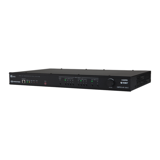
DMPS3-4K-150-C
3-Series
DigitalMedia
Presentation System 150
®
TM
DO
Mount the DMPS3-4K-150-C
Mount the DMPS3-4K-150-C into a standard 19-inch rack, onto a flat surface, or under a table as appropriate for the installation.
Mounting into a Rack
The DMPS3-4K-150-C occupies 1U of rack space.
WARNING:
To prevent bodily injury when mounting or servicing this unit in a rack, observe the following guidelines:
• When mounting this unit in a partially filled rack, load the rack from the bottom to the top with the heaviest component at the bottom of the rack.
• If the rack is provided with stabilizing devices, install the stabilizers before mounting or servicing the unit in the rack.
NOTE:
Observe the following guidelines when installing equipment in a rack:
• Elevated Operating Ambient - If installed in a closed or multi-unit rack assembly, the operating ambient temperature of the rack environment may be
greater than room ambient temperature. Therefore, consideration should be given to installing the equipment in an environment compatible with the
maximum ambient temperature (Tma) specified by the manufacturer.
• Reduced Airflow - Installation of the equipment in a rack should be such that the amount of airflow required for safe operation of the equipment is not
compromised.
• Mechanical Loading - Mounting of the equipment in the rack should be such that a hazardous condition is not achieved due to uneven mechanical
loading.
• Circuit Overloading - Consideration should be given to the connection of the equipment to the supply circuit and the effect that overloading of the
circuits might have on overcurrent protection and supply wiring. Appropriate consideration of equipment nameplate ratings should be used when
addressing this concern.
• Reliable Earthing - Reliable earthing of rack-mounted equipment should be maintained. Particular attention should be given to supply connections other
than direct connections to the branch circuit (e.g., use of power strips).
To mount the unit into a rack, use the two included rack ears and do the following:
1. Using a #1 or #2 Phillips screwdriver, remove the three cover screws closest to the front panel on the left or right side of the unit.
2. Position a rack ear so that its mounting holes align with the holes vacated in step 1.
3. Secure the ear to the unit using the three screws removed in step 1.
4. Repeat steps 1 through 3 to attach the remaining ear to the other side of the unit.
5. Secure the unit to the rack using two rack mounting screws (not included) for each rack ear.
Mounting onto a Flat Surface
To mount the unit onto a flat surface or to stack the unit on top of other equipment, use the four rubber feet included with the unit.
DO
Check the Box
QUANTITY
PRODUCT
4
Rubber Feet
1
Power Cord, 3-Prong, 6 Feet
1
Crestron
®
STIRP IR Emitter Probe
2
Interface Connector, Plug, 3-Pin
2
Interface Connector, Plug, 4-Pin
2
Interface Connector, Plug, 5-Pin
2
Rack Ear
4
Bracket, Table Mount
1
Important Safety Instructions
Not included: Cables, rack mount screws, and table mount screws
Mounting under a Table
To mount the unit under a table, use the four included table mount brackets and do the following:
1. Using a #1 or #2 Phillips screwdriver, remove the two cover screws closest to the front panel on the left or right side of the unit.
2. Position a table mount bracket so that its mounting holes align with the holes vacated in step 1.
3. Secure the bracket to the unit using the two screws removed in step 1.
4. Repeat steps 1 through 3 to attach a bracket to each of the three remaining positions as shown in the illustration below.
5. Attach the four table mount brackets to the underside of the table using four mounting screws (not included).
DO
Make Connections to the DMPS3-4K-150-C
Make connections to the front and rear panels of the DMPS3-4K-150-C as required for the application.
Making Connections to the Front Panel
Connect the COMPUTER port (USB Type B) to a USB Type A port on a PC (USB 2.0 A/B cable not included).
D M
4 K
P R E S E N T A T I O N
S Y S T E M
COMPUTER
PWR
NET
MSG
HW-R
SW-R
IR IN
PC Running
Crestron Toolbox™
PART NUMBER
2002389
2001134
2001137
2003575
2003576
2003577
2032122
2041951
2018589
INPUT SELECT
AUTO
VGA
HDMI
DM
1
2
3
4
1
2
3
4
1
2
VOLUME
DMPS3-4K-150-C