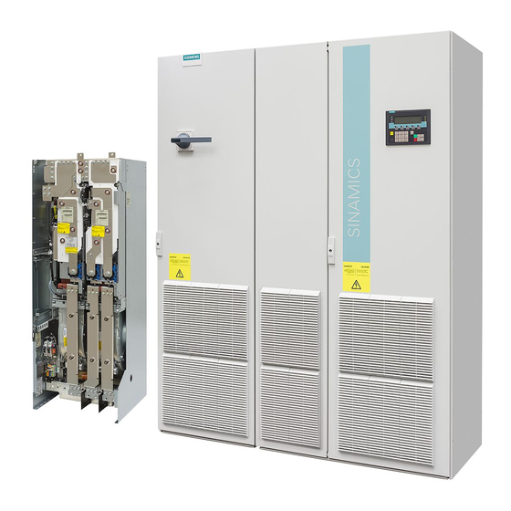
Siemens SINAMICS G130 Betriebsanleitung - Seite 27
Blättern Sie online oder laden Sie pdf Betriebsanleitung für Industrielle Ausrüstung Siemens SINAMICS G130 herunter. Siemens SINAMICS G130 46 Seiten. Line filter
Auch für Siemens SINAMICS G130: Betriebsanleitung (24 seiten), Betriebsanleitung (26 seiten), Betriebsanleitung (46 seiten), Betriebsanleitung (24 seiten), Betriebsanleitung (31 seiten), Betriebsanleitung (30 seiten), Betriebsanleitung (28 seiten), Betriebsanleitung (30 seiten), Betriebsanleitung (22 seiten), Betriebsanleitung (28 seiten), Betriebsanleitung (30 seiten), Betriebsanleitung (34 seiten), Betriebsanleitung (46 seiten), Betriebsanleitung (26 seiten), Betriebsanleitung (26 seiten), Betriebsanleitung (28 seiten), Betriebsanleitung (42 seiten), Betriebsanleitung (46 seiten), Betriebsanleitung (24 seiten), Betriebsanleitung (24 seiten), Betriebsanleitung (30 seiten), Betriebsanleitung (42 seiten), Betriebsanleitung (38 seiten), Betriebsanleitung (28 seiten), Betriebsanleitung (22 seiten), Betriebsanleitung (24 seiten)

