Siemens SIPART PS2 Installationsanweisung - Seite 3

Blättern Sie online oder laden Sie pdf Installationsanweisung für Industrielle Ausrüstung Siemens SIPART PS2 herunter. Siemens SIPART PS2 4 Seiten. Mounting bracket kit
Auch für Siemens SIPART PS2: Betriebsanleitung (28 seiten), Installationsanweisung (4 seiten), Hardware-Installationshandbuch (30 seiten), Technische Beschreibung (26 seiten), Kompakt-Bedienungsanleitung (35 seiten), Anleitung zur Installation des Kits (9 seiten), Installationsanweisung (11 seiten)
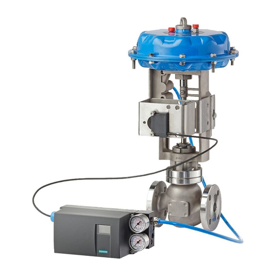
Siemens SIPART PS2 Installationsanweisung
Linkage U – 1) Place the feedback lever on the positioner input shaft and tighten the clamp
screw. 2) Insert the threaded end of the feedback pin into the feedback lever slot and loosely
secure the pin with the supplied nut and lockwasher.
5. Plug the positioner Y1 port – Select a compatible pipe plug: 1/4 NPT or G1/4. Place a small amount
of non-hardening pipe sealing compound on the threads of the 1/4 NPT plug. Refer to the drawing
below and thread the selected plug into the Y1 port.
A single-acting position is recommended for this application. A double acting
positioner (with Y2 port) is not recommended.
6. Remove the factory-installed Y1 sealing screw and O-ring – Refer to the drawing below and use a
TORX® wrench to remove the sealing screw and O-ring from the back of the positioner.
7. Linkage P – Size the feedback pin:
1) Refer to the figure on page 1 and orient the positioner to the actuator as shown.
2) Place the positioner against the manifold.
3) Rotate the feedback lever against the feedback pin and measure the length of pin that extends
beyond the lever. The pin must extend beyond the lever by a minimum of 1/8" but must not
contact the positioner or any other item throughout its range of motion.
4) If the pin must be shortened, mark the pin where it is to be cut and remove the pin from the
actuator. Cut the pin to length and remove any burs from the cut end; a slight bevel will make
inserting the pin into the lever slot easier. Do not score the pin where it will ride in the feedback
lever slot.
5) Thread the pin into the stem block and tighten.
Note
1. Y1 Port, actuating pressure
2. Positioner input shaft
3. P
Port, Supply air
Z
4. n/a
5. Exhaust air outlet
3
15900-766