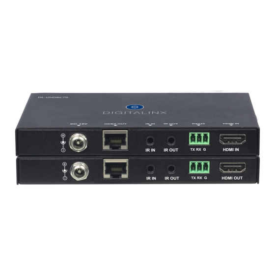
DigitaLinx DL-UHDRC70 Benutzerhandbuch - Seite 10
Blättern Sie online oder laden Sie pdf Benutzerhandbuch für Extender DigitaLinx DL-UHDRC70 herunter. DigitaLinx DL-UHDRC70 16 Seiten. Hdbaset extender
Auch für DigitaLinx DL-UHDRC70: Handbuch zur Schnellinstallation (8 seiten), Handbuch zur Schnellinstallation (8 seiten), Handbuch zur Schnellinstallation (6 seiten)

DL-UHDRC70 Owners Manual
Connecting IR Control
The DL-UHDRC70 is capable of transmitting bi-directional IR signals through the HDBaseT circuit. The
UHDRC70 comes with 2 IR receivers (eye) and 2 IR emitters (flashers) so you can control devices from either end
of the extender circuit.
Passing IR Signals:
The DL-
to any of the electronics, the extenders should be powered off while inserting or removing any
IR components. Inserting an IR transmitter into the IR IN port may damage the IR circuit for that
Source Device Control using IR
Attach the IR emitter to the IR receiver of the source device, insert the TS 3.5 mm plug of the emitter to the IR
OUT port of the DL-UHDRC70 transmitter. Insert the TS 3.5 mm plug of the IR receiver (eye) to the IR IN port
of the DL-UHDRC70 receiver. Point the source device IR remote at the display location where the IR receiver is
located, IR signals will now travel through HDBaseT to the DL-UHDRC70 transmitter side where the IR emitter is
attached to the source device.
Remote Display using IR
Attach the IR emitter to the IR receiver of the display device, insert the TS 3.5 mm plug of the emitter to the IR
OUT port of the DL-UHDRC70 receiver. Insert the TS 3.5 mm plug of the IR receiver (eye) to the IR IN port of the
DL-UHDRC70 transmitter. Point the source device IR remote at the source device location where the IR receiver
is located, IR signals will now travel through HDBaseT to the DL-UHDRC70 receiver side where the IR emitter is
attached to the display device.
Source / Display Control from Control System
To pass 3rd party IR system signals through the DL-HD70, such as a control system, connect the TS connector
of the IR-AC coupling cable (provided) to the IR output port of the control system and connect the TRS connec-
tor of the IR-AC cable to the IR IN to either transmitter or receiver of the DL-UHDRC70.
Tx or Rx Extender IR Input
10
UHDRC70
is capable of passing IR signals between 33 and 55 KHz. To prevent damage
Tip: +5V DC
Ring: IR Signal
Sleeve: Ground (GND)
IR Signal
Note: Voltage on Tip from RX may be differnt for non Liberty Devices
+5V DC Lifted
Ground (GND)
DL-
Sleeve: Ground (GND)
Tip: IR Signal
To Control system or
IR hub output
