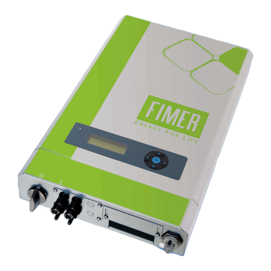
Fimer R25 Series Benutzerhandbuch - Seite 6
Blättern Sie online oder laden Sie pdf Benutzerhandbuch für Modem Fimer R25 Series herunter. Fimer R25 Series 16 Seiten. Grid connected pv inverter internal and external gsm modem user guide for single-phase inverter
Auch für Fimer R25 Series: Handbuch (12 seiten)

________________________________________________________________________________
Prerequisites for using a GSM modem
Sufficiently good reception at the installation location. Always check this is the case before
you begin to use the GSM modem. (The provider/seller of the SIM card can assist you in
this.)
SIM card with GPRS and GSM data function .
We currently recommend you use an INTEL MD566X 56K V.90 Data, Fax, and Voice
Chipset external modem for connecting to a PC to make GSM connections.
Check that the SIM card functions properly before you commence actual communication
(PIN, phone number and GPRS).
Aerial
Connecting the Internal Modem
If the inverter is already equipped with the GSM modem option card, all that is required is an aerial
cable with a FME connector. The aerial should be installed at exposed a position as possible in
order to ensure good reception. If the aerial used has a magnetic base, it must be mounted on a
metallic, horizontal surface that is as large as possible.
Please refer to the Chapter 7 ("Setting the Modem Functions at the Inverter")of this manual
for setting the inverter.
Installing the Modem Option Card inside the slot of the Inverter
Introductory remarks: Inverters that conform to degree of protection IP 54 cannot be retrofitted
because the sealing material could become damaged by such a measure. In that case please keep in
contact with Fimer.
Inverters that conform to degree of protection IP 21 must be retrofitted by specially trained
personnel only. Caution! When carrying out such work, remember you are dealing with a piece of
equipment that carries high voltage levels. Furthermore, always observe the relevant rules and
regulations relating to electrostatic discharge (ESD)!
Fimer will not accept liability or claims made under warranty for any malfunctions or damage
caused through errors made by you while installing the equipment in object
The installation procedure of the equipment is as described below:
1. Switch off and disconnect the inverter
Disconnect the inverter from the mains voltage (e.g. by opening the mains fuse or
removing the Wieland power plug).
Disconnect all poles of the solar generator from the inverter and set the DC
switch-disconnector on 0: the inverter must no longer feed in power
Wait 5 minutes until the voltage in the inverter has been completely discharged.
2. Disconnect all connectors from the inverter (especially if the electronics are supplied
with power by a plug-in AC adapter during the night)
3. Open the cover of the IP 21 enclosure
Unscrew all 8 screws on the side.
Carefully remove the cover.
Pull the ribbon cable from the cover carefully out of the microprocessor card.
4. Now unscrew all 4 screws of the option card slot at the bottom on the inverter and
remove the option card slot dummy plate
_____________________________________________________________________________
4
