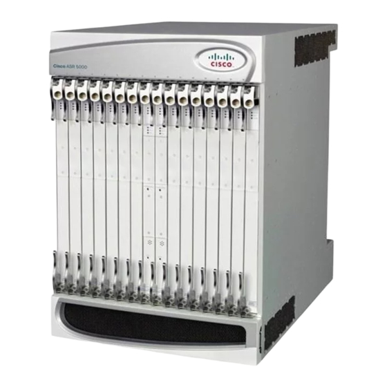
Cisco ASR 5000 Installationshandbuch - Seite 35
Blättern Sie online oder laden Sie pdf Installationshandbuch für Gateway Cisco ASR 5000 herunter. Cisco ASR 5000 37 Seiten. Applying power and verifying the installation
Auch für Cisco ASR 5000: Installationshandbuch (18 seiten), Installationshandbuch (33 seiten), Installationsverfahren (8 seiten)

Applying Power and Verifying the Installation
RCC Standby LED States
The Standby LED on the RCC indicates that software is loaded on the card. The card is ready to provide a
path for data or signalling traffic from a line card to a redundant packet processing card. This LED is on during
normal operation for both installed RCCs.
If the LED is not green, use the troubleshooting information in the table to diagnose the problem.
Table 31: RCC Standby LED States
Color
Green
None
Completing Initial System Configuration
After power is applied to the chassis and the ASR 5000 has successfully booted, the command line interface
(CLI) appears on a terminal connected to the Console port of the SPIO.
The initial configuration requires completing the following tasks via the CLI:
• Configuring the system for remote access
• Configuring the management interface with a second IP Address (optional)
• Configuring system timing
• Enabling CLI timestamping
• Configuring system administrative users
• Configuring TACACS+ for system administrative users (optional)
• Configuring a chassis key
• Configuring virtual MAC addresses
• Configuring packet processing and line card availability
• Configuring line card and SPIO port redundancy
• Configuring ASR 5000 link aggregation (optional)
• Configuring ORBEM and the Web Element Manager (optional)
Description
Troubleshooting
Card is in standby mode
This is the normal operating mode.
Card is not receiving
Verify that the Run/Fail LED is green. If so, the card is receiving
power OR
power and POST test results are positive. If it is off, refer to
Run/Fail LED States, on page 33
Card in Active Mode
Check the state of the Active LED. If it is green, the card is in
active mode and the RCC is actively routing traffic from a line
card installed behind a packet processing card that has failed. See
Checking the LEDs on Packet Processing Cards, on page 12
determine which packet processing card has failed.
Completing Initial System Configuration
for troubleshooting information.
ASR 5000 Installation Guide
RCC
to
35
