Epson Perfection 1670 Photo Service-Handbuch - Seite 27

Blättern Sie online oder laden Sie pdf Service-Handbuch für Software Epson Perfection 1670 Photo herunter. Epson Perfection 1670 Photo 46 Seiten. Color image scanner
Auch für Epson Perfection 1670 Photo: Informationen zum Produkt (7 seiten), Start Handbuch (9 seiten), Handbuch (11 seiten), Update (1 seiten), Produkt-Support-Bulletin (17 seiten), Produkt-Support-Bulletin (12 seiten), Wichtige Sicherheitshinweise (4 seiten), Broschüre & Specs (2 seiten)
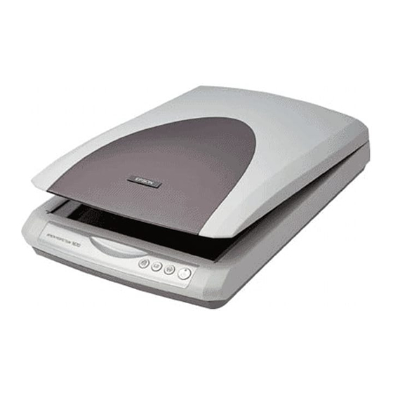
Epson Perfection 1670 Photo Service-Handbuch
EPSON Perfection 1670 Photo/Perfection 1270
4.
Disconnect the Inverter Cable Connector and Fluorescent Lamp Connector connected
to the TPU Inverter Board.
5.
Remove the two screws (CBP M3x8) that are securing the Inverter Board, and remove
the Inverter Board together with the Protective Sheet.
6.
Open the Protective Sheet, and remove the TPU Inverter Board.
When reinstalling the TPU Inverter Unit, connect the Inverter Cable
in the following procedure.
1.
Insert the Stopper of the Inverter Cable into the socket of the
TPU Inverter Unit. Fit the Stopper with its delta mark on the
outside.
2.
Set the Expansion Tube of the Inverter Cable into the notch of
the TPU Inverter Unit.
3.
Put the Inverter Cable on the rail of the TPU Inverter Unit,
hold down the Inverter Cable with your finger, and connect it
to the TPU Unit.
Expansion Tube
Stopper
DISASSEMBLY/ASSEMBLY
Delta mark
Socket
Inverter Cable
Disassembly Procedure
CBP (M3x8)
Tightening torque 6-8kgfcm
Inverter Connector Cable
Figure 2-28. Disconnection of Connector Cable
Protective Sheet
TPU Inverter Board
Figure 2-29. Removal of TPU Inverter Board
Revision B
Fluorescent Lamp Connector
27