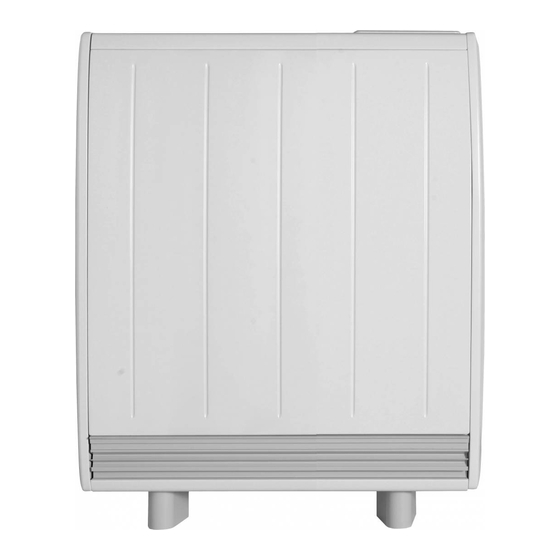
Dimplex Quantum series Installations- und Betriebshandbuch - Seite 5
Blättern Sie online oder laden Sie pdf Installations- und Betriebshandbuch für Elektrischer Heizer Dimplex Quantum series herunter. Dimplex Quantum series 12 Seiten.
Auch für Dimplex Quantum series: Schnellstart-Handbuch (12 seiten)

Please scan the QR code to access detailed Quantum Installation Instructions.
Included are a view of the product, how to unpack the unit, install exterior
components, install internal components, securing to the wall, sizing and fi tting
instructions, electrical connections and set up.
NOTE:
Read these instructions carefully before proceeding any further with the installation
Product Clearances
WARNING: DO NOT PLACE
OBJECTS WITHIN 300mm OF
THE FRONT OF THE HEATER,
150mm AT EITHER SIDE OR
250mm FROM THE TOP
1. Place the heater fl at on the ground with arrows printed
on the base of the carton pointing upwards.
Open the carton at the bottom, slide the heater out of the
carton by at least 200mm exposing the feet and the fi xing
kit located within the packaging on the right hand side.
Remove the feet and the fi xing kit. (Fig. 2)
Note - Foot screws are in the fi xing kit.
WARNING
The appliance must be securely
fi xed to the wall. The installed
appliance could weigh up to
165kg and if it falls off the wall
it could cause severe personal
injury or death. It is the
responsibility of the installer
to ensure that the appropriate
wall fi xing is used and that the
fl oor is capable or bearing the
full weight.
- 5 -
Installation Instructions
Fig. 2
Fig. 1
250 mm
300 mm
Y
2. Secure the feet to the heater using all the screws
provided (4 per heater). For models QM050, QM070 and
QM100 two locations are possible indicated by X and Y
markings visible on the base of the heater.
Ensure the feet are fi xed at the location holes marked with
an 'X', (Fig. 3/3B).
However, if this is a replacement heater check the pitch of
the feet and choose the appropriate fi xing positions - either
X or Y.
The spacing between the feet when secured in location X
and Y is indicated in the table below.
Models
Feet spacing in X Feet spacing in Y
QM 050
QM 070
QM 100
QM 125 & 150
Fig. 3
X
Y
X
248
198
306
370
422
572
532
n/a
