Pioneer Super Tuner IIID DVH-P5000MP Installationshandbuch
Blättern Sie online oder laden Sie pdf Installationshandbuch für Auto-Empfänger Pioneer Super Tuner IIID DVH-P5000MP herunter. Pioneer Super Tuner IIID DVH-P5000MP 8 Seiten. 2004 mobile entertainment systems
Auch für Pioneer Super Tuner IIID DVH-P5000MP: Benutzerhandbuch (34 seiten), Benutzerhandbuch (24 seiten), Betriebshandbuch (4 seiten)
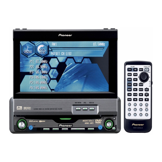
DVH-P5000MP
This product conforms to CEMA cord colors.
Le code de couleur des câbles utilisé pour ce produit est con-
forme à CEMA.
Printed in Japan
Imprimé au Japon
<CRD3792-A> UC
<KSNNF/03C00001>
Connecting the Units
Connecting the Units
• Speakers connected to this unit must be high-
Notes
power types with minimum rating of 50 W and
• This unit is for vehicles with a 12-volt battery
impedance of 4 to 8 ohms. Connecting speak-
and negative grounding. Before installing it in
ers with output and/or impedance values other
a recreational vehicle, truck, or bus, check the
than those noted here may result in the speak-
battery voltage.
ers catching fire, emitting smoke, or becoming
• To avoid shorts in the electrical system, be
damaged.
sure to disconnect the ≠ battery cable before
• When this product's source is switched ON, a
beginning installation.
control signal is output through the blue/white
• Refer to the owner's manual for details on
lead. Connect to an external power amp's sys-
connecting the power amp and other units,
tem remote control or the car's Auto-antenna
then make connections correctly.
relay control terminal (max. 300 mA 12 V DC).
• Secure the wiring with cable clamps or adhe-
If the car features a glass antenna, connect to
sive tape. To protect the wiring, wrap adhesive
the antenna booster power supply terminal.
tape around them where they lie against metal
• When an external power amp is being used
parts.
with this system, be sure not to connect the
• Route and secure all wiring so it cannot touch
blue/white lead to the amp's power terminal.
any moving parts, such as the gear shift, hand-
Likewise, do not connect the blue/white lead to
brake, and seat rails. Do not route wiring in
the power terminal of the auto-antenna. Such
places that get hot, such as near the heater
connection could cause excessive current
outlet. If the insulation of the wiring melts or
drain and malfunction.
gets torn, there is a danger of the wiring short-
• To avoid short-circuiting, cover the discon-
circuiting to the vehicle body.
nected lead with insulating tape. Especially,
• Don't pass the yellow lead through a hole into
insulate the unused speaker leads without fail.
the engine compartment to connect to the
There is a possibility of short-circuiting if the
battery. This will damage the lead insulation
leads are not insulated.
and cause a very dangerous short.
• To prevent incorrect connection, the input side
• Do not shorten any leads. If you do, the protec-
of the IP-BUS connector is blue, and the out-
tion circuit may fail to work when it should.
put side is black. Connect the connectors of
• Never feed power to other equipment by cut-
the same colors correctly.
ting the insulation of the power supply lead of
the unit and tapping into the lead. The current
capacity of the lead will be exceeded, causing
overheating.
• When replacing fuse, be sure to use only fuse
of the rating prescribed on this unit.
• Since a unique BPTL circuit is employed, never
wire so the speaker leads are directly
grounded or the left and right ≠ speaker leads
are common.
Connecting the Units
• If this unit is installed in a vehicle that does not
have an ACC (accessory) position on the igni-
tion switch, the red lead of the unit should be
connected to a terminal coupled with ignition
switch ON/OFF operations. If this is not done,
the vehicle battery may be drained when you
are away from the vehicle for several hours.
(Fig. 1)
ACC position
No ACC position
Fig. 1
• The black lead is ground. Please ground this
lead separately from the ground of high-cur-
rent products such as power amps.
If you ground the products together and the
ground becomes detached, there is a risk of
damage to the products or fire.
• Cords for this product and those for other
products may be different colors even if they
have the same function. When connecting this
product to another product, refer to the sup-
plied Installation manuals of both products
and connect cords that have the same func-
tion.