Whirlpool UXT4030AD Installationsanleitung und Gebrauchs- und Pflegeanleitung - Seite 6

Blättern Sie online oder laden Sie pdf Installationsanleitung und Gebrauchs- und Pflegeanleitung für Lüftungshaube Whirlpool UXT4030AD herunter. Whirlpool UXT4030AD 28 Seiten. 30" and 36" (76.2 and 91.4 cm) range hood
Auch für Whirlpool UXT4030AD: Installationsanleitung und Gebrauchs- und Pflegeanleitung (24 seiten), Installationsanleitung und Gebrauchs- und Pflegeanleitung (24 seiten), Installationsanleitung und Gebrauchs- und Pflegeanleitung (24 seiten), Installationsanleitung und Gebrauchs- und Pflegeanleitung (24 seiten)
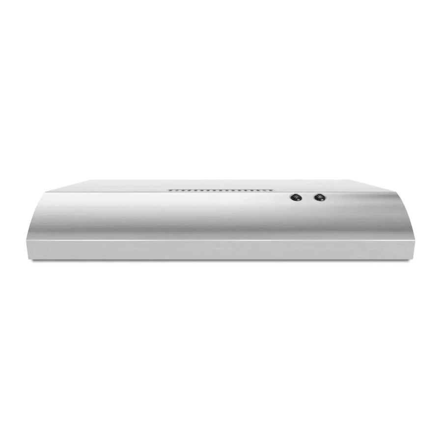
Whirlpool UXT4030AD Installationsanleitung und Gebrauchs- und Pflegeanleitung
NOTES:
Depending on your model, determine which venting method
to use: roof, wall or non-vented (recirculating).
It is recommended that the vent system be installed before
the range hood is installed. Go to "Venting System" in the
"Installation Requirements" section if you need assistance.
Before making cutouts, make sure there is proper clearance
within the ceiling or wall for the vent system.
1. Disconnect power
WARNING
Electrical Shock Hazard
Disconnect power before servicing.
Replace all parts and panels before operating.
Failure to do so can result in death or electrical shock.
2. Mark Hole Locations
Align the exterior edge of the mounting brackets with the exterior
edges of the upper cabinet.
IMPORTANT: The brackets should touch the upper cabinet.
With a pencil, mark the upper holes on the brackets.
6

INSTALLATION INSTRUCTIONS

3. Install Brackets
Using a #2 Phillips screwdriver, install the drywall anchors.
Using #8-18 x 1" (4.2 x 25 mm) flat-head #2 Phillips screws,
install the mounting brackets using the upper holes.
NOTE: For installations to a surface other than drywall, it is
recommended that a qualified contractor determine the
anchoring method.

4. Prepare Range Hood

Set the range hood on its back on a covered surface.
Using a #2 Phillips screwdriver, remove the rectangular
damper attached with 3.5 x 9.5 mm screws.
Using a #2 Phillips screwdriver, remove the electrical box
cover.
Using a flat-blade screwdriver, remove the appropriate power
supply knockout.