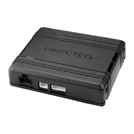
Directed 403.TL10 Installationshandbuch - Seite 6
Blättern Sie online oder laden Sie pdf Installationshandbuch für Zubehör für Kraftfahrzeuge Directed 403.TL10 herunter. Directed 403.TL10 19 Seiten.

Wiring diagram
Refer to "Pre-installation and application warnings" for important information, such as the description of each special note referenced in the diagram (
D2D Port
(-) Ground
(-) Ground
(AC) Tach Input
(-) Parking Lights Output
(+) 12V Input
(+) Ignition 2 Output
(+) Accessory Output
(+) Starter 2 Output
(+) Starter 1 Output
(+) Ignition 1 Output
6
403.TL10 2.29 2017 Toyota Camry (H Key)
©2022 VOXX•DEI LLC. All rights reserved.
Headlight Switch
10
9
8
7
6
5
4
3
2
20
19
18
17
16
15
14
13
12
Autolight: Green, pin 20
Cut
(+) Ignition 2:
Pink, pin 1
(+) Accessory:
White, pin 2
(+) Starter 2
Lt. Green, pin 3
4
3
2
1
Ignition
Connector
8
7
6
5
(+) 12V:
Green, pin 5
(+) Starter:
Blue, pin 7
(+) Ignition 1:
Black, pin 6
Diagnostic Connector OBDII
HS CAN High: Tan/Black: 3
1
11
TPMS Ignition Interrupt (conn. side): Yellow: 8
TPMS Ignition Interrupt (veh. side): Orange/Yellow: 9
Autolight Interrupt (conn. side): Orange/Red: 10
Autolight Interrupt (veh. side): Yellow/Red: 11
(AC) Tach Output: Violet/White: 5
SIL Data: Yellow/Black: 10
RDA: Orange/Black: 11
Body ECU
Connector
Body ECU Connector
(middle conn. left side of steering column)
6
5
4
16
18
17
15
14
13
26
30
29
28
27
25
RDA: Blue, pin 16
HS CAN High:
SIL Data:
Blue, pin 6
Gray, pin 7
1
8
9
16
HS CAN Low:
White, pin 14
HS CAN Low: Tan: 4
3
2
1
12
11
10
9
8
7
24
23
22
21
20
19
).
XKD2D65
