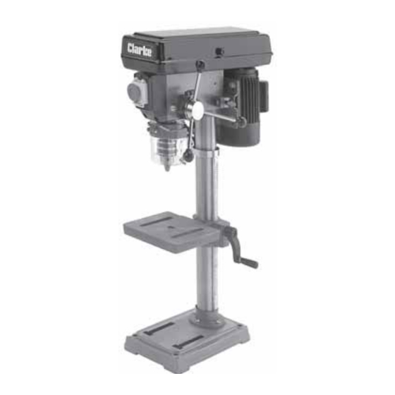
Clarke METALWORKER CDP15F Betriebs- und Wartungsanleitung - Seite 14
Blättern Sie online oder laden Sie pdf Betriebs- und Wartungsanleitung für Elektrowerkzeug Clarke METALWORKER CDP15F herunter. Clarke METALWORKER CDP15F 19 Seiten. 12 speed drill press

MAINTENANCE
or maximum performance, it is essential that the Drill Press is properly maintained. Always inspect
F
before use. Any damage should be repaired, and faults rectified.
If the mains lead is worn or cut, or damaged in any way, it should be replaced immediately.
Please refer to the trouble shooting chart on page 15 . If you are unable to rectify any faults, please
contact your local dealer or Clarke International Service Division on 020 8988 7400 for assistance.
Monthly
(When in constant use)
1. Check tightness of mounting bolts, and, head and column securing set screws.
2. Check belt for wear, and replace if frayed or damaged in any way.
3. Blow out any dust that may have accumulated in the motor fan.
4. Apply a thin coat of wax paste or light oil to the table and column, for lubrication, and
to help prevent corrosion.
Lubrication
All bearings are packed with grease at the factory and require no further lubrication.
After use
Remove all swarf from the machine and thoroughly clean all surfaces.
Components should be dry, with machined surfaces lightly oiled.
Always remove drill bits, and store in a safe place.
CUTTING SPEEDS
Factors which determine the best speed to use in any drill press operation are:
• Kind of material being worked • Size of hole • Quality of cut desired • Type of Drill
Generally, the smaller the drill, the greater the required RPM. In soft material, the speed should
be higher than for hard materials.
As a general guide, the drill speed for a given drill bit size, is according to the table below.
Speed Range
(RPM)
Wood
Zinc
Die-cast
Alum &
Brass
Plastic
Cast Iron
& Bronze
Mild Steel
& Malleable
Cast Steel
& Med Carbon mm
Stainless
and Tool Steel
2180 -
1580
2580
in
1/4
3/8
mm
6.4
9.5
in
3/16
1/4
mm
4.8
6.4
in
1/8
3/16
mm
3.2
4.8
in
1/8
3/16
mm
3.2
4.8
in
3/32
1/8
mm
2.4
3.2
in
1/16
3/32
mm
1.6
2.4
in
3/64
1/16
1.2
1.6
in
1/32
3/64
mm
0.8
1.2
1290 -
500 -
830
1350
540
5/8
-
-
16
-
-
3/8
1/2
5/8
9.5
12.5
16
3/8
1/2
11/16
9.5
12.5
17.5
5/16
7/16
1/2
7.9
11
12.5
1/4
11/32
1/2
6.4
8.75
12.5
5/32
1/4
3/8
4
6.4
9.5
1/8
3/16
5/16
3.2
4.8
7.9
1/16
1/8
1/4
1.6
3.2
6.4
320 -
210 -
420
280
-
-
-
-
-
-
-
-
-
-
-
-
5/8
-
16
-
5/8
-
16
-
1/2
-
12.5
-
7/16
9/16
11
14.5
3/8
1/2
9.5
12.5
14
