Directed Xpresskit DBALL2 Installationshandbuch - Seite 4

Blättern Sie online oder laden Sie pdf Installationshandbuch für Durch Schlösser Directed Xpresskit DBALL2 herunter. Directed Xpresskit DBALL2 18 Seiten. Ford5 remote start ready (rsr) installation
Auch für Directed Xpresskit DBALL2: Installationshandbuch (12 seiten), Installationshandbuch (19 seiten), Handbuch (14 seiten), Installationshandbuch (13 seiten), Installationshandbuch (14 seiten), Installationshandbuch (19 seiten), Installationshandbuch (16 seiten), Installationshandbuch (20 seiten), Installationshandbuch (15 seiten), Handbuch für Installation und Kurzanleitung (16 seiten), Installationshandbuch (18 seiten), Installationshandbuch (16 seiten), Installationshandbuch (18 seiten), Installationshandbuch (16 seiten), Handbuch (19 seiten)
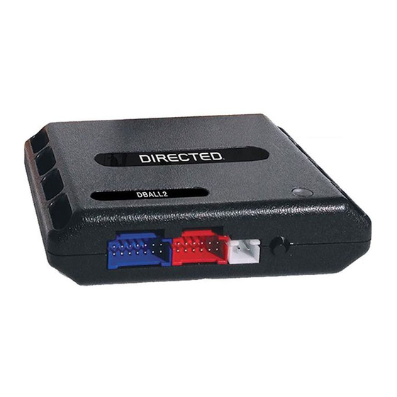
Directed Xpresskit DBALL2 Installationshandbuch
Platform: DBALL2
Firmware:
HYUNDAI4

Type

1
- Vehicle Wiring Reference Chart
Wire Information
Function
Color
Santa Fe (Smart Key) 2013-2015
12V
Red
PTS 1
Orange/Black
PTS 2
Yellow/Orange
C-CAN High Green
C-CAN Low
Orange
Parking LightsPink
Starter
Pink
Ignition
Green
Accessory
Yellow
EMS COM
White/Orange
B-CAN High Blue
B-CAN Low
Red
Santa Fe Sport (Smart Key) 2013-2015
12V
Red
PTS 1
Orange/Black
PTS 2
Yellow/Orange
C-CAN High Green
C-CAN Low
Orange
Parking LightsPink
Starter
Pink
Ignition
Green
Accessory
Yellow
EMS COM
White/Orange
B-CAN High Blue
B-CAN Low
Red
Locating components in the vehicle
Driver Kick Panel
Remote Start Ready
Pin Polarity Location
1
(+)
I/P-B, front of dash fuse box. White
3
(-)
M04, PTS switch.
2
(-)
M04, PTS switch.
6
Data
OBDII.
14
Data
OBDII.
15
(-)
M01-L, headlight switch.
11
(+)
EM11, driver kick panel.
21
(+)
EM11, driver kick panel.
3
(+)
EM11, driver kick panel.
32
Data
EM11, driver kick panel.
24
Data
MF11, driver kick panel.
33
Data
MF11, driver kick panel.
(RSR)
Installation
Connector Information
Color Pin
Black
Black
Black
Black
White 16
Black
Black
Black
Black
White 48
White 48
Black
Black
Black
Black
White 16
Black
Black
Black
Black
White 48
White 48
Rev.: 20170814
4
12
12
16
16
46
46
46
46
4
12
12
16
16
46
46
46
46
© 2017 Directed. All rights reserved.
Page 4