Directed Xpresskit DBALL2 Installationshandbuch - Seite 5

Blättern Sie online oder laden Sie pdf Installationshandbuch für Durch Schlösser Directed Xpresskit DBALL2 herunter. Directed Xpresskit DBALL2 19 Seiten. Ford5 remote start ready (rsr) installation
Auch für Directed Xpresskit DBALL2: Installationshandbuch (12 seiten), Installationshandbuch (19 seiten), Installationshandbuch (18 seiten), Handbuch (14 seiten), Installationshandbuch (13 seiten), Installationshandbuch (14 seiten), Installationshandbuch (16 seiten), Installationshandbuch (20 seiten), Installationshandbuch (15 seiten), Handbuch für Installation und Kurzanleitung (16 seiten), Installationshandbuch (18 seiten), Installationshandbuch (16 seiten), Installationshandbuch (18 seiten), Installationshandbuch (16 seiten), Handbuch (19 seiten)
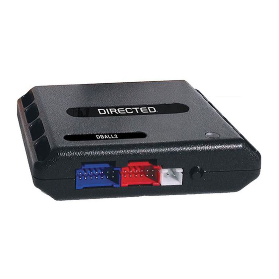
Directed Xpresskit DBALL2 Installationshandbuch
Platform: DBALL2
Firmware: CHRYSLER7 Remote Start Ready Installation (RSR)
Installation without T-Harness
Important!
The Hood Pin and Remote Start Safety Override Switch are mandatory safety devices, but are NOT supplied with the DBALL.
Brake Connector
1
2
3
4
Brake:
Dk.Green/Lt. Green,
pin 1
Immo. Data:
White/Lt. Green, pin 5
6
5
4
3
2
1
PTS Switch
(+) PTS:
Violet/
(black connector)
Brown,
pin 4
(-) Driver Door Trigger: Violet
Harness
in driver kick panel
Remote Start Safety Override Switch: If grounded, the vehicle will NOT start.
[1]
HS CAN2 connections are required for heated seats.
[2]
Hood pin: Required only when factory hood pin is not available.
[3]
With the exception of the OBDII Diagnostic connector, all adapters are displayed from the wire side (unless specified otherwise).
(-) Ground: Black, pin 4
HS CAN2 High: Gray, pin 3
[2]
1
9
HS CAN2 Low: White, pin 11
[2]
HS CAN Low: Yellow, pin 14
(+) 12V: Red, pin 16
HS CAN High: Tan/Black: 3
HS CAN Low: Tan: 4
HS CAN2 High: Orange/Green: 5
[2]
HS CAN2 Low: Orange/Brown: 6
[2]
Immo. Data (vehicle side): Yellow: 8
Immo. Data (conn. side): Orange/Yellow: 9
(+) Brake Output: Yellow/Red: 11
(+) 12V: Brown/Red: 12
(+) 12V: Red: 13
(-) Ground: Black: 14
(+) PTS Output: Gray/Black: 7
(MUX) Parking Lights Output: Violet/Brown: 9
Immo. Data (vehicle side): Yellow/Black: 10
(-) RAP Off: Orange/Black: 11
6
5
Vehicle
4
Headlamp Switch
3
(6-pin Connector)
(MUX) Parking Lights:
2
White/Brown, pin 3
1
HS CAN High:Gray/White, pin 6
8
OBDII
Diagnostic
16
Connector
RF
Prog. Button
DBALL2
LED
Rev.: 20160610
Hood Pin
[3]
Remote Start Safety
[1]
Override Switch
6: White/Black: (-) Hood
You can connect to either a XL202
RFTD OR a SmartStart module.
Refer to the SmartStart/XL202
Installation Notes for more information.
© 2016 Directed. All rights reserved.
Page 4