Directed Xpresskit DBALL2 Посібник з монтажу - Сторінка 5

Переглянути онлайн або завантажити pdf Посібник з монтажу для За замками Directed Xpresskit DBALL2. Directed Xpresskit DBALL2 19 сторінок. Ford5 remote start ready (rsr) installation
Також для Directed Xpresskit DBALL2: Посібник з монтажу (12 сторінок), Посібник з монтажу (19 сторінок), Посібник з монтажу (18 сторінок), Посібник (14 сторінок), Посібник з монтажу (13 сторінок), Посібник з монтажу (14 сторінок), Посібник з монтажу (16 сторінок), Посібник з монтажу (20 сторінок), Посібник з монтажу (15 сторінок), Посібник зі встановлення та короткий довідник (16 сторінок), Посібник з монтажу (18 сторінок), Посібник з монтажу (16 сторінок), Посібник з монтажу (18 сторінок), Посібник з монтажу (16 сторінок), Посібник (19 сторінок)
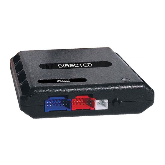
Directed Xpresskit DBALL2 Посібник з монтажу
Platform: DBALL2
Firmware: CHRYSLER7 Remote Start Ready Installation (RSR)
Installation without T-Harness
Important!
The Hood Pin and Remote Start Safety Override Switch are mandatory safety devices, but are NOT supplied with the DBALL.
Brake Connector
1
2
3
4
Brake:
Dk.Green/Lt. Green,
pin 1
Immo. Data:
White/Lt. Green, pin 5
6
5
4
3
2
1
PTS Switch
(+) PTS:
Violet/
(black connector)
Brown,
pin 4
(-) Driver Door Trigger: Violet
Harness
in driver kick panel
Remote Start Safety Override Switch: If grounded, the vehicle will NOT start.
[1]
HS CAN2 connections are required for heated seats.
[2]
Hood pin: Required only when factory hood pin is not available.
[3]
With the exception of the OBDII Diagnostic connector, all adapters are displayed from the wire side (unless specified otherwise).
(-) Ground: Black, pin 4
HS CAN2 High: Gray, pin 3
[2]
1
9
HS CAN2 Low: White, pin 11
[2]
HS CAN Low: Yellow, pin 14
(+) 12V: Red, pin 16
HS CAN High: Tan/Black: 3
HS CAN Low: Tan: 4
HS CAN2 High: Orange/Green: 5
[2]
HS CAN2 Low: Orange/Brown: 6
[2]
Immo. Data (vehicle side): Yellow: 8
Immo. Data (conn. side): Orange/Yellow: 9
(+) Brake Output: Yellow/Red: 11
(+) 12V: Brown/Red: 12
(+) 12V: Red: 13
(-) Ground: Black: 14
(+) PTS Output: Gray/Black: 7
(MUX) Parking Lights Output: Violet/Brown: 9
Immo. Data (vehicle side): Yellow/Black: 10
(-) RAP Off: Orange/Black: 11
6
5
Vehicle
4
Headlamp Switch
3
(6-pin Connector)
(MUX) Parking Lights:
2
White/Brown, pin 3
1
HS CAN High:Gray/White, pin 6
8
OBDII
Diagnostic
16
Connector
RF
Prog. Button
DBALL2
LED
Rev.: 20160610
Hood Pin
[3]
Remote Start Safety
[1]
Override Switch
6: White/Black: (-) Hood
You can connect to either a XL202
RFTD OR a SmartStart module.
Refer to the SmartStart/XL202
Installation Notes for more information.
© 2016 Directed. All rights reserved.
Page 4