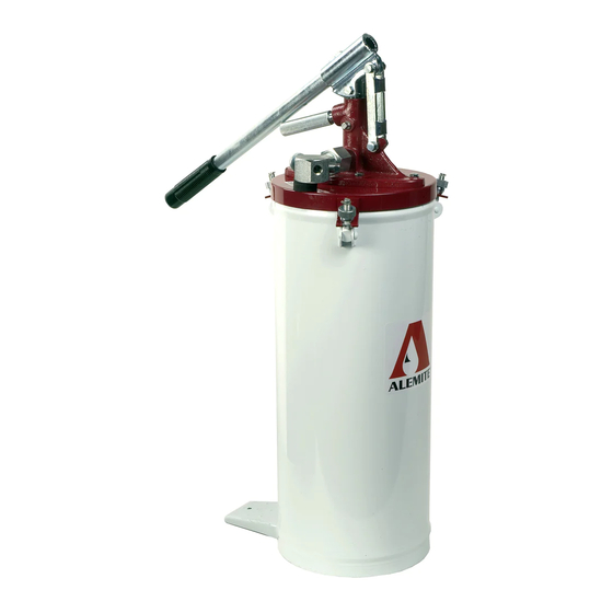
Alemite 6713-4 Service-Handbuch - Seite 7
Blättern Sie online oder laden Sie pdf Service-Handbuch für Water Pump Alemite 6713-4 herunter. Alemite 6713-4 10 Seiten. High-pressure bucket pump

High-Pressure Bucket Pump
Clean and Inspect
NOTE: Use the repair kit for replacement parts. Make
sure all the components are included in the kit before
discarding used parts.
1. Clean all metal parts in cleaning solvent. The solvent should be
environmentally safe.
2. Inspect all parts for wear and/or damage.
• Replace as necessary.
3. Inspect Plunger (18) closely. Use a magnifying glass to detect any
score marks.
• Replace as necessary.
4. Closely inspect the mating surfaces of Valve (36) and Valve Seat
(35) for any imperfections Ensure a smooth and clean contact is
obtained when assembled.
5. Inspect the mating surfaces of Check Valve (22).
Item
Part No.
Description
No.
41
317302
Nut, Coupling
42
54288
Adapter, Coupling
43
Gasket (Copper)
44
Seat, Ball
45
Washer (Copper)
46
Ball, 13/32 " Dia.
47
300520
Adapter, Coupling
48
Spring
49
300518
Spacer
Legend:
Part numbers left blank (or in italics) are not available separately
designates a repair kit item - See Figure 2-B for part number
Figure 2-C Check Valve Assembly Model 54282 - Exploded View
Alemite Corporation
Numeric Order
Qty
Notes
Part # (Item #)
1
54288
1
54290
1
54393
1
171700-26
1
300518
1
300519
1
300520
1
300596
1
317302
7
EXAMPLE: Place Ball
(46) in Ball Seat (44).
W h i l e s u p p o r t i n g t h e
Ball, fill the Ball Seat
with solvent. Make sure
no leakage occurs.
Assembly
IMPORTANT: Prior to
assembly, lubricate the
upper threads (slotted) of
Primer Rod (33) in clean
grease. Also, lubricate
th e b o ttom o f Plun ger
(18) and both O-Rings
(19). See Figure 2-B.
Pump Tube
NOTE: Refer to Figure 3
for a section view of the
pump tube assembly.
1. Install and seat both lubricated O-
Rings (19) into Body (20).
CAUTION
Install Plunger (18) and Primer
Rod (33) with care. Damage to O-
Rings can occur.
2. Install Plunger (18) [stem end first]
into the top of the Body.
• See Figure 2-B for the proper
hole.
(42)
3. Install Primer Rod (33) [slotted end
first] into the bottom of the Body.
(43)
• Gently rotate the Primer Rod past
(45)
the O-Ring.
(46)
4. Screw both Adapters (16) onto the
(49)
Plunger and Primer Rod.
• Make sure the cotter pin hole
(44)
aligns with the slot in the Plunger
(47)
and Primer Rod.
(48)
5. Secure the Adapters to the Plunger
(41)
and Primer Rod with Cotter Pins
(17).
SER 6713-4
Revision (2-02)
