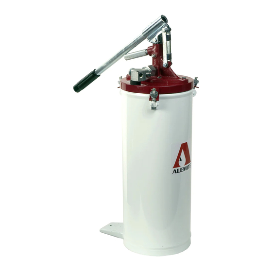
Alemite 6713-4 Service-Handbuch - Seite 8
Blättern Sie online oder laden Sie pdf Service-Handbuch für Water Pump Alemite 6713-4 herunter. Alemite 6713-4 10 Seiten. High-pressure bucket pump

SER 6713-4
6. Install and seat Gasket (31) into the
bottom of the Body.
7. Install Plug (32) into the Body.
• Tighten the Plug securely.
8. Screw Tube (38) into the Body.
• Do not tighten at this time.
9. Install Stop Washer (37) and Valve
(36) [small diameter first] onto the
Primer Rod.
10. Screw Valve Seat (35) into the
Tube.
• Tighten the components securely.
11. Screw Priming Plunger (34) onto
the Primer Rod.
• Make sure the holes are aligned.
12. Install Cotter Pin (17).
13. Screw Handle (25) into the Body as
required.
14. Install Bleed Valve Screw (26) into
the Body as required.
Check Valve Assembly
15. Install Pressure-Relief Valve Screw
(29) into Bushing (28).
16. Install Retaining Ring (27) that
secures the Valve Screw to the
Bushing.
17. Screw the Pressure-Relief Valve
Screw Assembly into Adapter
Body (24) [port with the drain
hole].
18. Screw Drain Tube (30) into the
Adapter Body.
NOTE: Refer to Figure
2-C for component identi-
fication on procedures
19-25.
19. Install and seat Spring (48), Spacer
(49) [large diameter first], Washer
(45), and Ball (46) into Coupling
Adapter (47).
Revision (2-02)
20. Screw Ball Seat (44) [with Loctite 242] into the Coupling Adapter.
• Tighten the Ball Seat to 200 inch-pounds (22.6 Nm).
21. Install Gasket (43) onto the Coupling Adapter.
22. Install Coupling Adapter (42) into Coupling Nut (41).
Figure 3 Pump Assembly Model 310750-4 - Section View
8
High-Pressure Bucket Pump
Refer to Figure 2-B Parts List
for Parts Identification
Alemite Corporation
