Clarke CONTRACTOR 6462119 Handbuch für Betrieb und Wartung - Seite 18
Blättern Sie online oder laden Sie pdf Handbuch für Betrieb und Wartung für Werkzeuge Clarke CONTRACTOR 6462119 herunter. Clarke CONTRACTOR 6462119 20 Seiten. Worktop jig

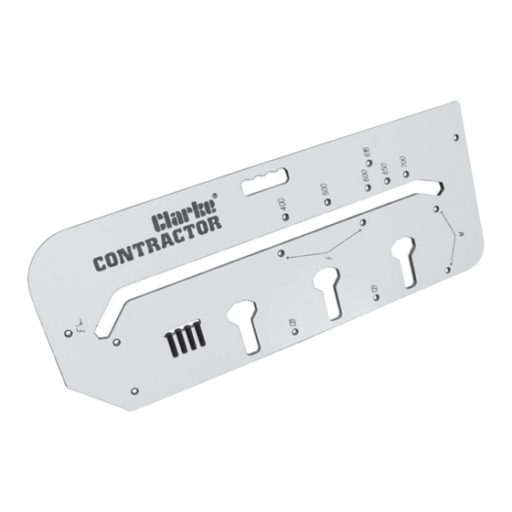
19. Fully insert 3 pins in the holes marked 'CB'.
20. Clamp the jig to the worktop ensuring all 3 pins are pushed firmly against the
worktop. Ensure clamps do not obstruct the router path.
21. Place the router into the front of one of the clamp bolt recesses, set the depth of
cut to 10mm max. Switch the router ON and machine the recess. When done,
switch the router OFF and wait for the cutter to stop spinning. Return the router to
the back again. Increase the depth of cut a further 10mm and machine the recess
again. When finished, switch the router OFF and wait for it to stop spinning.
22. Repeat step 21 for the other 2 recesses (other 3 recesses for 900mm worktops).
Recesses must be no deeper than 20mm maximum.
Shaping Corners
1.
Cutting
2.
- Position the router (guide bush) on the edge of the jig at the post form end,
ensure the router base is flush on the jig surface. Set the cut depth to 10mm max.
3. Switch the router ON and slowly move the router following the edge of the jig.
Switch OFF and wait for the cutter to stop spinning.
4. Lift the router off the jig and return it to the start position again, increase the depth
of cut a further 10mm and make a second pass. Keep repeating steps 3 & 4 until
the cut is complete, i.e. the cutter is below the bottom of the worktop.
9. Switch the router OFF and wait for it to stop spinning, remove the router and jig,
store them away safely for reuse.
Post Form Edge
-17-
IMPORTANT
- Position jig on worktop as in Fig. 24 below.
Cut Direction
Fig. 24
15mm
15mm
