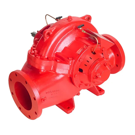
Armstrong 4600 HSC series Installations- und Betriebsanleitung - Seite 6
Blättern Sie online oder laden Sie pdf Installations- und Betriebsanleitung für Water Pump Armstrong 4600 HSC series herunter. Armstrong 4600 HSC series 16 Seiten. Horizontal split case fire pumps. 12x8x18f

i n s ta l l at i o n &
o p e r at i n g i n s t r u c t i o n s
6
1.4. alignment
The flexible coupling compensates for temperature changes
and permits shafts end movement without interference; it will
not compensate for misalignment. Faulty alignment will result in
noisy pump operation, reduced bearing life, and excessive
coupling wear.
• Carefully verify the alignment after the foundation bolts
have been properly tightened
• Alignment should be again verified after piping is installed
and unit has operated under normal conditions at operat-
ing temperature
• To verify alignment, place a straight edge across the cou-
pling as shown; this must rest evenly on both rims at top,
bottom and both sides
• With a pair of inside calipers or thickness gauge, check
distance between coupling halves at points where straight
edge was used; distance must be equal at all points
1.5. minimum fittings
If minimum fittings recommended by n.f.p.a. 20 are supplied
loose, they should be installed as follows:
testing alignment
angular
misalignment
feeler taper
perfect
alignment
Horizontal split case
fire pumps
straight gauge
feeler gauge
circulation relief valve (not supplied with diesel driven
pumps)
• Install Circulation Relief Valve at the casing discharge (al-
ways before the check valve)
• Set pressure at the minimum suction pressure plus the pump
rated pressure raised to the next higher 5 lb. increment
• Circulation relief valve and stuffing box should then be piped
to drain
automatic air release valve
• Install automatic air release valve on top of pump casing
to vent casing and suction piping of air and vapor before
start-up.
suction and discharge gauges
• The following gauges are required to measure both suction
and discharge pressures, and must be supplied with all fire
pumps to ensure close check on pump performance:
a 3½" dial combination pressure and vacuum suction gauge
b 3½" dial discharge pressure gauge
c ¼" cocks with lever handle
parallel
alignment
straight gauge
