Armstrong OB 2000PT Anweisungen für Installation, Betrieb und Wartung - Seite 2
Blättern Sie online oder laden Sie pdf Anweisungen für Installation, Betrieb und Wartung für Kontrolleinheit Armstrong OB 2000PT herunter. Armstrong OB 2000PT 6 Seiten. Pressure/temperature regulating valve

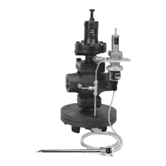
Figure 2-1 OB 2000PT
H
H1
ØA
10-1/2"
(267 mm)
A.
Assembly
1. Do not lose the bellows follower (10), union
gasket (45) and pre-formed copper D pipe (46) as
shown in Figure 2-2.
2. Insert copper union gasket (45) into union fitting,
tighten the union joint and install pre-formed
copper D (46) pipe as shown in Figures 2-1
and 2-2.
B.
Installation of OB 2000PT Main Valve
1. Align flow direction with direction of arrow cast
into body.
2. Install OB 2000PT perpendicular to horizontal
piping so that the diaphragm chamber is located
at the bottom.
C.
Installation of Capillary System
(See Figures 2-1, 2-2 and 4-1 on Page 4)
1. Once the valve body is installed, insert bellows
follower (10), which was packaged with the
capillary system inside the sensor bellows (35)
with the flat side down toward the capillary
bellows. Turn the adjusting screw (15) counter
clockwise to relieve spring tension. Attach
capillary system to temperature pilot valve body
and tighten capillary ring union (22).
See Figure 2-2.
2. Thermal Bulb (23) may be installed in any
position. However, care should be taken so that at
least three quarters of the thermal bulb is
touching the fluid being heated.
3. Screw in bushing (24) first and attach thermal
bulb (23) with packing nut (36). See Figure 4-1,
Page 4.
G
9-1/2"
(241 mm)
1" NPT
Thermal Well
3/4" NPT
Figure 2-2
(28)
Lock
Nut
(30B) "B" Fitting
OB-2000
Main Valve
4. Do not twist or bend capillary sharply. Bending
radius of capillary should not be more than 1-1/2".
Position capillary so that it does not touch steam
lines, hot water lines, or regulator.
5. Install a thermometer into the fluid close to the
thermal bulb. See Figure 1-1 Page 1.
6. When using the thermal bulb (23) in a pipe, make
sure the thermal bulb is installed in a location
where the fluid freely flows around the bulb.
7. If a thermal well is used. Make sure heat transfer
compound is applied to the thermal bulb before
installation into the well.
D.
Regulating Method
Important: Temperature control is best achieved
when the delivery pressure is the lowest steam
pressure capable of maintaining the desired
temperature at maximum load.
1. Open valve on drip leg to allow inverted bucket
steam trap to drain condensate on OB 2000PT
inlet.
Table 2-1.
Capillary Range
Number on
Adjusting
Dial
18 - 59 50 - 97 86 - 144 131 - 201 176 - 260 239 - 361
0
12
39
1
28
59
2
43
77
3
57
93
4
70
109
2
Adjusting
Screw (27)
Pressure
Pilot
"D" Pipe (46)
(45) Union
Gasket Copper
Adjusting
Lock
Screw (15)
Nut
(16)
Bellows Follower (10)
Tee
(33)
Sensor Bellows (35)
Capillary
Ring Union (22)
"C" Fitting (30C)
(Not Shown)
Capillary System Range °F
72
113
154
99
142
192
120
169
225
136
196
257
153
223
297
OB-2000P
Pilot Valve
214
266
307
352
410
