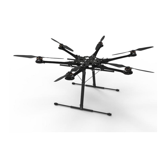
dji S800 Handbuch
Blättern Sie online oder laden Sie pdf Handbuch für Drohnen dji S800 herunter. dji S800 3 Seiten. Retractable landing gearfor spreading wings
Auch für dji S800: Benutzerhandbuch (16 seiten)

Retractable Landing Gear
2013.01.24 Revised
Introduction
The retractable landing gear is designed for the S800 frame in order to provide a better perspective in
aerial-filming / photography work. By using a 2-position switch channel of the R/C transmitter, you can
control the landing gear to retract remotely. The retractable landing gear will not block the view of the
camera lens, making smooth shooting in all directions possible.
Disclaimer & Warning
Thank you for purchasing this DJI product. Please regularly visit the S800 web page at
www.dji-innovations.com. This page is updated regularly. Any technical updates and manual corrections will
be available on this web page. Due to unforeseen changes or product upgrades, the information contained
in this manual is subject to change without notice.
Please strictly follow the manual to assemble and use the retractable landing gear. As DJI Innovations has
no control over use, setup, final assembly, modification or misuse, no liability shall be assumed nor accepted
for any resulting damage or injury. By the act of use, setup or assembly, the user accepts all resulting
liability. DJI Innovations accepts no liability for damage(s) or injuries incurred directly or indirectly from the
use of this product.
DJI and S800 are registered trademarks of DJI Innovations. Names of product, brand, etc., appearing in this
manual are trademarks or registered trademarks of their respective owner companies. This product and
manual are copyrighted by DJI Innovations with all rights reserved. No part of this product or manual shall
be reproduced in any form without the prior written consent or authorization of DJI Innovations. No patent
liability is assumed with respect to the use of the product or information contained herein.
©2012
DJI Innovations. All Rights Reserved.
for Spreading Wings S800
V 1.2
1
Assembly & Connection
The part with the control board attached is defined as left, the other part is right. Make sure to make a
distinction between the left and the right servos.
STEP1
Servo Installation
(If the servos have already been installed, please skip this step.)
1. Define and mark two
HS-7954SH
servos from
2. Connect the left servo to the [L] port on the control board, and the right servo to the [R] port.
3. Keep pressing the SET button with the aid of a small tool, and then power on. You will see the yellow
LED flashes quickly, and then wait until the servos have finished their position initialization.
4. Make sure the servo arm is parallel to the servo's center line (shown in the following Fig).
5. Power off, and assemble the left and right servos to the left and the right parts of the landing gear.
Tips: If you use your own servos, it is recommended to use dedicated programmer from Hitec to enlarge
the servo travel from 120° to 150°, and then install servos by the above steps. Servos from DJI have been
enlarged servo travel.
STEP2
Mechanical Assembly
1. Assemble the left and the right parts respectively, and then fix the screws at the joints with appropriate
screw thread lock.
2. Connect the left and right parts with the connecting rod.
3. For safety reasons, make sure to connect the springs to both parts.
4. Assemble the battery Bracket, referring to the "S800 User Manual".
STEP3
Electrical Connections
1. Plug the cables from the servos into the correct ports on the control board. Make sure the right servo is
connected to the [R] port, and the left servo to the [L] port.
2. Connect the required 2-position switch channel of the R/C receiver to the [IN] port.
Ser voArmInstallation
ine
Servo
CenterL
Arm
RightS
er vo
Ser vo
Finished
Right art of the anding ear
P
Left art of the
GimbalF
©2012
DJI Innovations. All Rights Reserved.
Hitec
as left servo and right servo.
Ser voAssembly
LeftS
ervo
ControlBoard
R
L
IN
DANGER!!!
DO NOT TOUCH!
RightSer vo
LED
LeftSer vo
L
G
SETButton
ReceiverChannel
anding ear
P
L
G
D
ront
irection
2
