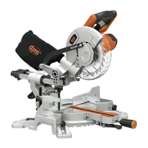
djm direct DJMSL8 Übersetzung der Originalbetriebsanleitung - Seite 7
Blättern Sie online oder laden Sie pdf Übersetzung der Originalbetriebsanleitung für Säge djm direct DJMSL8 herunter. djm direct DJMSL8 14 Seiten.

Remove all packaging material from the machine and the accessories
provided.
Before starting the operation of the machine for the first time, check
if all parts listed in the box content section have been supplied
Note: Check the power tool for possible damage. Before further use
of the machine, check that all protective devices are fully functional.
Any lightly damaged parts must be carefully checked to ensure
flawless operation of the tool. All parts must be properly mounted
and all conditions fulfilled that ensure faultless operation.
Damaged protective devices and parts must be immediately replaced
by an authorised service centre.
Always tighten the locking knob (20)&(12) firmly before
sawing.
Otherwise the saw blade can become wedged in the workpiece.
Transportation
Lift the mitre saw only when the saw arm is locked in the down
position, the saw is switched off and the plug is removed from the
power point.
Only lift the saw by the operating handle (5) or outer castings. Do not
lift the saw using the guards.
Stationary or Flexible Mounting
To ensure safe handling, the machine must be mounted on a level
and stable surface (e. g., workbench) prior to using.
Mounting to a Working Surface
– Fasten the power tool with suitable screw fasteners to the working
surface. The mounting holes serve for this purpose.
or
– Clamp the power tool with commercially available screw clamps by
the feet to the working surface.
Mounting to a Saw Stand
Any universal saw stand which will accept mounting holes 420mm
wide by 350mm in length will suffice
Read all safety warnings and instructions included with the
worktable. Failure of observing safety warnings and instructions can
lead to electrical shock, fire and/or cause serious injuries.
Assemble the worktable properly before mounting the power tool.
Perfect assembly is important in order to prevent the risk of
collapsing.
– Mount the power tool in transport position on the saw stand.
Dust/Chip Extraction
Dusts from materials such as lead-containing coatings, some wood
types, minerals and metal can be harmful to one's health. Touching
or breathing-in the dusts can cause allergic reactions and/or lead to
respiratory infections of the user or bystanders.
Certain dusts, such as oak or beech dust, are considered as
carcinogenic, especially in connection with wood-treatment additives
(chromate, wood preservative). Materials containing asbestos may
only be worked by specialists.
– Always use dust extraction or the Dust bag (11) provided
– Provide for good ventilation of the working place.
– It is recommended to wear a P2 filter-class respirator.
Observe the relevant regulations in your country for the materials to
be worked.
The dust/chip extraction can be blocked by dust, chips or workpiece
fragments.
– Switch the machine off and pull the mains plug from the socket
outlet.
– Wait until the saw blade has come to a complete stop.
– Determine the cause of the blockage and correct it.
Integrated Dust Extraction.
– Insert the dust bag firmly onto the machine
During sawing, the dust bag must never come in contact with moving
tool components.
Always empty the dust bag in good time.
External Dust Extraction
For dust extraction, you can also connect the extraction port to a
vacuum hose (internal Ø 40 mm).
The dust extractor must be suitable for the material being worked.
When vacuuming dry dust that is especially detrimental to health or
carcinogenic, use a special dust extractor.
Changing the Blade
–Make sure that the electrical plug is removed from the power point.
–Push down on the operating handle (3) and pull there lease knob (4)
to disengage the saw arm (3).
–Raise the saw arm (3) to its highest position.
–Loosen the cover plate screw about 2 turns with a Phillips
screwdriver. Do not remove this screw from the tool.
–Pull the rotating blade guard (8) down. When the rotating blade
guard (8) is positioned over the upper fixed blade guard (6) it is
possible to access the blade bolt.
–Lift and hold up the lower blade guard (8) to expose the threaded
blade bolt.
–Hold the rotating guard (8) up and press the spindle lock button
(22). Rotate the blade until the spindle locks.
–Use the 6 mm hex key provided to loosen and remove the blade
bolt. (Loosen in a clockwise direction as the blade screw has a left
hand thread).
6
